Active vs passive cell balancing and how to validate balancing logic before pack build
汽车
11 / 08 / 2026

核心要点
- Cell balancing sets how much of a pack’s capacity is usable, and its logic matters more on LFP cells with flat voltage curves.
- Passive balancing is cheap and simple, while active balancing recovers capacity faster at higher cost and control complexity.
- Balancing logic can be proven on HIL against a simulated pack with realistic cell spread, long before the first module is built.
Cell balancing decides how much of a battery pack’s capacity you can actually use, and its control logic is far cheaper to prove on a simulated pack than on a real one that took months to build.
Chemistry trends are making that logic harder to get right. LFP cells accounted for over 55% of EV batteries deployed globally in 2025, and their flat voltage curve hides state of charge differences across most of the operating range. A balancing algorithm that works on NMC cells can sit idle on an LFP pack until the imbalance is already large.
Whichever balancing hardware you choose, the decisions that matter live in firmware. When to balance, how much and on which cells all depend on estimates that are hard to verify once the pack is sealed, so the strongest programs prove those decisions on HIL before the first module is assembled.
What cell balancing does inside a battery pack
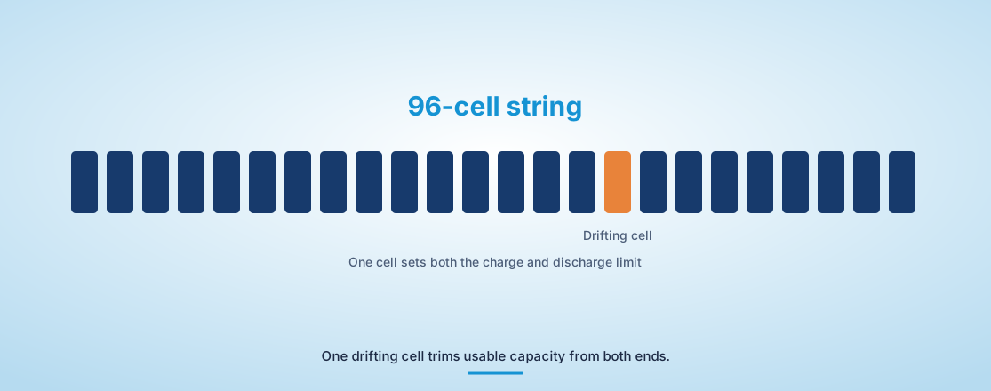
Cell balancing equalizes the state of charge of series-connected cells so the pack isn’t limited by its weakest cell. Without it, small differences in capacity, self-discharge and temperature drift apart over cycles until one cell hits its voltage limit while others still hold usable energy.
The effect compounds in large packs. A 96-cell string can only charge until its highest cell reaches the upper limit and discharge until its lowest cell reaches the lower limit, so one drifting cell trims capacity from both ends. In a storage rack with thousands of cells, that loss turns directly into energy the operator can’t sell.
How passive cell balancing bleeds off excess charge
Passive cell balancing switches a resistor across any cell whose voltage or estimated state of charge sits above its neighbours, turning the excess energy into heat. It’s simple, inexpensive and reliable, which is why most automotive packs still use it.
The trade-off is speed and heat. Balancing currents are usually tens to a couple of hundred milliamps, so correcting a large imbalance can take many hours, and the resistors add heat inside a module that thermal design already constrains. Most systems balance near the top of charge or during rest periods to keep that heat manageable.
Cost pressure keeps passive designs dominant. Average battery prices declined by 8% in 2025, and every component in the battery management system faces the same pressure, so a resistor and a switch per cell remains hard to beat on price.
“In a grid storage rack that cycles twice a day, imbalance that passive balancing can’t correct between cycles becomes stranded capacity, and the economics of active hardware look very different.”
How active cell balancing moves energy between cells
Active cell balancing transfers charge from stronger cells to weaker ones using capacitors, inductors or small DC-DC converters. Energy moves instead of burning, so balancing is faster and recovers capacity that passive methods throw away as heat.
Topologies range from switched capacitors that shuttle charge between neighbours to isolated converters that move energy between any cell and the whole string. The more flexible designs balance during charge and discharge, which matters in applications where the pack is rarely at rest.
The added complexity shows up in control. Active balancing needs accurate state estimates for every cell, coordination between many converters and protection against faults in the balancing circuits themselves. A stuck converter can drain a cell instead of helping it, and the firmware has to detect that quickly.
Those demands make active balancing a strong fit for second-life batteries, mixed-age modules and large stationary systems where capacity recovery pays for the hardware.
“Balancing errors cut both ways.”
Active versus passive cell balancing at pack and rack scale
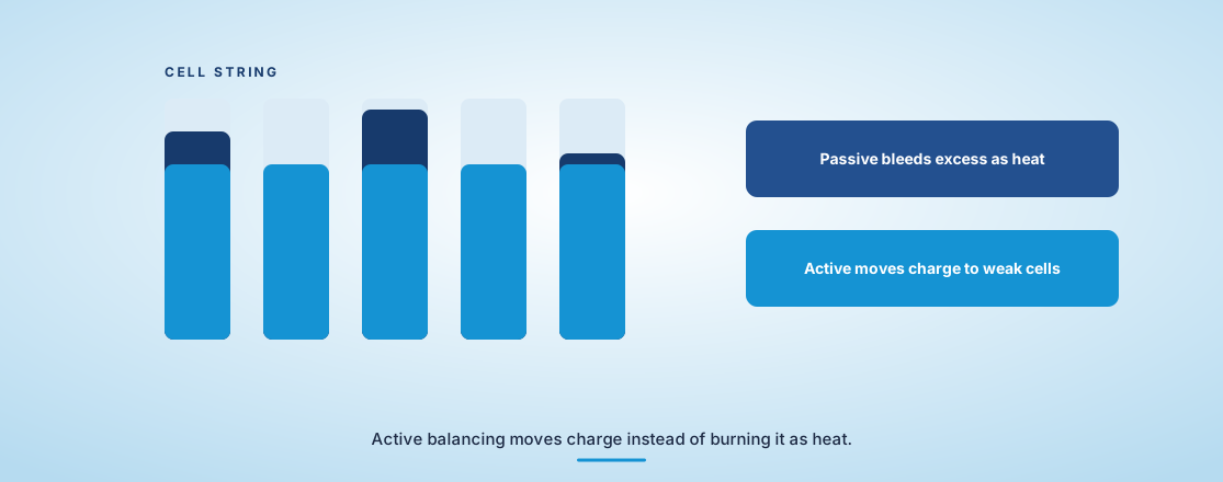
The main difference between active and passive cell balancing is what happens to the excess energy. Passive balancing burns it as heat through resistors, while active balancing moves it to cells that need it, which makes active designs faster and more efficient but more complex and costly.
Scale changes the arithmetic. In a car, a few hours of slow passive balancing overnight is usually enough. In a grid storage rack that cycles twice a day, imbalance that passive balancing can’t correct between cycles becomes stranded capacity, and the economics of active hardware look very different.
| Factor | Passive balancing | Active balancing |
| Energy handling | Excess charge is dissipated as heat in resistors | Excess charge is transferred to weaker cells |
| Balancing speed | Slow, often hours for a large imbalance | Faster, with higher balancing currents |
| 硬件成本 | Low, with one resistor and switch per cell | Higher, with converters or capacitor networks |
| Control complexity | Simple threshold or estimate-based switching | Coordinated control of many converters and fault detection |
| 最合适 | Cost-sensitive automotive packs that rest regularly | Large storage racks, second-life packs and high-cycling systems |
Why cell balancing matters for battery life
Cell balancing matters for battery life because unbalanced cells age unevenly. The cell that repeatedly reaches the voltage limits sees more stress, degrades faster and drags down the pack’s usable capacity, which shortens the useful life of every cell around it.
Balancing errors cut both ways. Too little balancing lets drift grow, while balancing on a wrong state of charge estimate can push a healthy cell out of line and create the imbalance it was meant to fix. That’s especially likely on LFP, where a small voltage error maps to a large state of charge error.
How to validate balancing logic on HIL before pack build
You validate balancing logic on HIL by connecting the real battery management system to a cell emulator that a real-time model of every cell in the pack controls. The emulator reproduces each cell’s voltage and temperature, so the controller balances against a simulated pack that behaves like the real one, including its drift.
The model is where the value comes from. You can assign each simulated cell its own capacity, resistance and self-discharge rate, then run hundreds of cycles in compressed time and watch how the balancing algorithm responds. Engineers using OPAL-RT battery HIL setups often seed those cell parameters from manufacturing data, so the virtual pack carries the same spread the production line will deliver.
Balancing test plans usually include a core set of scenarios.
- A single cell with low capacity in an otherwise uniform string
- A temperature gradient across the module during fast charge
- State of charge estimation drift on LFP cells in the flat region
- A failed balancing switch or converter on one channel
- Long rest periods followed by deep discharge
Each scenario can be repeated with a modified algorithm the same day. On a physical pack, the same comparison would need weeks of cycling and a fresh pack for every variant. You’d also be limited to the cell spread that pack happened to have, while the model lets you test the worst spread your supplier’s specification allows.
What early balancing validation saves a battery program
Early balancing validation saves cycling time, prototype packs and warranty exposure, because balancing faults found on a simulated pack cost a firmware change instead of a module replacement. It also gives the team evidence that the algorithm handles cell spread it hasn’t yet seen on real hardware.
We see battery teams move faster once balancing is treated as a software problem with a test bench of its own. With OPAL-RT real-time simulation emulating every cell, the balancing logic that reaches the first pack has already met thousands of imperfect cells.
电力系统
11 / 13 / 2026
Grid forming inverters, how they work and how to test them
A technical explainer on how grid forming inverters and their control loops work, and how to test grid forming control through faults, islanding and weak grids.

电力系统
11 / 03 / 2026
Medium voltage and grid interactive UPS systems for data centers
An engineering guide to medium voltage and grid interactive UPS systems for data centres, covering static transfer switches, modular designs and pre-commissioning validation.

电力电子
11 / 01 / 2026
Why high frequency SiC and GaN converters outrun real-time simulation
A perspective on why high frequency SiC and GaN converters outrun classic real-time solvers and what engineers now need to validate them as designed.