
核心要点
- Grid forming inverters set their own voltage and frequency, which gives weak, inverter-heavy grids the support synchronous machines used to provide.
- The hardest grid forming control cases combine low grid strength with faults, phase jumps or islanding, and they can’t be staged safely on a live network.
- Controller HIL followed by power hardware testing gives operators repeatable evidence that a plant holds voltage and frequency through every grid code scenario.
Grid forming inverters keep weak, inverter-heavy grids stable by creating their own voltage and frequency reference, and their control only earns trust after it has been tested through faults, islanding and weak grid conditions in real time.
Solar PV capacity additions surpassed 600 GW in 2025 for the first time, and most of that capacity connects through inverters that follow the grid instead of holding it up. As synchronous machines retire, operators are asking new inverter-based plants to provide the inertia, voltage strength and fault behaviour that rotating machines used to supply for free.
Grid forming control is the answer most system operators have converged on, and it moves the risk from the hardware to the control code. That’s why the test plan matters as much as the inverter itself, because the scenarios that matter most are the ones nobody wants to stage on a live network.
How a grid forming inverter creates its own voltage reference
A grid forming inverter behaves like a voltage source behind an impedance. It generates its own internal voltage magnitude and phase angle, then adjusts them based on the power it delivers. Because it doesn’t wait to measure the grid before responding, it supports voltage and frequency from the first instant of a disturbance.
Picture a remote wind farm connected through a long, high impedance line. A grid following inverter on that line has to lock onto a voltage that sags and jumps every time the farm’s own output changes, and its phase locked loop can lose track entirely. A grid forming inverter sets the voltage at its terminals and lets power flow settle to match, which is exactly what a weak connection needs.
The control loops inside a grid forming converter
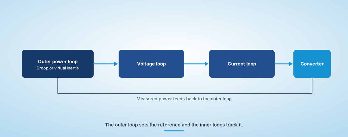
Most grid forming converters use an outer power loop that sets the internal frequency and voltage, and inner voltage and current loops that track those references while limiting current. The outer loop usually follows droop, virtual synchronous machine or dispatchable virtual oscillator control, each trading response speed against damping.
Droop control is the simplest to reason about. Frequency falls in proportion to active power and voltage falls with reactive power, so several units share load without communication. Virtual synchronous machine control adds an emulated inertia term, which slows the frequency response but gives operators the rotating machine behaviour their studies assume.
The inner loops are where most field issues start. When a fault pulls voltage down, the converter has to limit current to protect its semiconductors while still behaving like a voltage source. Many designs switch to a current limited mode for a few cycles, and the handover back to voltage control is where you’ll find oscillations, phase jumps and loss of synchronism if the gains aren’t tuned for the grid the unit actually sits on.
None of these loops can be judged in isolation. A virtual inertia setting that looks well damped against a stiff grid can ring against a weak one, so the loops have to be evaluated against the impedance the plant will really see.
Why grid forming inverter frequency response matters during disturbances
Grid forming inverter frequency response decides how much the grid frequency falls in the first second after a generator trips. A unit with synthetic inertia slows the rate of change of frequency immediately, which buys time for slower reserves to act before under-frequency load shedding begins.
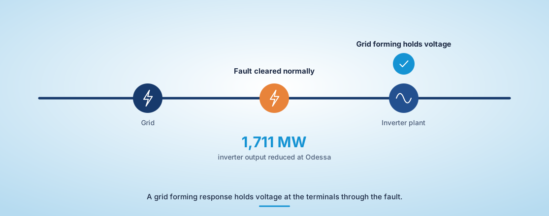
The value of that first second became clear in Texas. A single-line-to-ground fault near Odessa in June 2022 was cleared normally, yet 1,711 MW of inverter-based resources unexpectedly reduced output, many through controls and protection settings that misread the event. A grid forming response would have held voltage and frequency at the terminals instead of backing off.
Frequency response is also where commercial pressure meets physics. Every megawatt-second of emulated inertia comes from headroom in the DC link or the battery, and that headroom has a cost. Testing tells you how much is enough for the grid in question, which is a better answer than the largest value the hardware allows.
“A plant that can show its fault response against a calibrated model of its own connection carries far more weight than one that cites a type test on a stiff bench.”
The test cases that expose weak grid forming control
The test cases that expose weak control combine low grid strength with a sudden event. Short circuit ratios below 2, phase angle jumps, deep balanced and unbalanced faults and unplanned islanding reveal tuning problems that steady state tests never touch.
Most grid codes now group these into a standard set of scenarios.
- Phase angle jumps of 10 to 40 degrees on the point of connection
- Rate of change of frequency steps of 1 to 2 Hz per second
- Three-phase and single-phase faults at low short circuit ratio
- Unplanned islanding with the inverter carrying the remaining load
- Black start of a dead bus followed by load pickup
“The inner loops are where most field issues start.”
How real-time simulation reproduces faults without risking hardware
Real-time simulation runs a detailed model of the grid at the same speed as wall-clock time, so the real inverter controller exchanges signals with a network that responds exactly as the site would. You can apply the same fault hundreds of times, change grid strength between runs and record every variable.
Controller hardware in the loop is usually the first stage. The production control board connects to a simulator running the power stage, filter and grid at microsecond timesteps, and the test team scripts the full fault library against it overnight. Teams using OPAL-RT simulators commonly run the same scripts again after every firmware change, so a gain adjustment for one grid code can’t silently break another.
The table summarizes what each test stage contributes.
| 测试阶段 | What it validates | What it can’t show |
| 离线 EMT仿真 | Control design choices and stability margins across many grid strengths | How the production code and processor timing behave on the real board |
| 控制器硬件在环 | Real firmware responding to faults, jumps and islanding in real time | Semiconductor stress and thermal limits, which stay modelled |
| 电力硬件在环 | A physical inverter exchanging real power with a simulated weak grid | Full plant scale, since amplifier ratings cap the tested power |
| Factory acceptance testing | Rated power operation and protection functions on the finished unit | Weak grid interaction, because test benches are usually stiff sources |
| Site commissioning | Compliance on the actual point of connection | Severe faults and islanding, which operators rarely allow on a live network |
Moving from controller tests to power hardware validation
Power hardware in the loop puts a physical inverter between a power amplifier and a real-time grid model, so real current flows while the grid stays simulated. It validates the combination of firmware, sensors and power stage, which controller tests alone can’t confirm.
Current limiting is the main reason to take this step. A controller test shows the limiter engaging at the right time, but only real hardware shows how measurement delay, sensor noise and switching ripple interact with the limiter during a deep fault. Those effects often decide if a unit stays synchronized after the fault clears.
What a credible grid forming test plan proves to operators
A credible grid forming test plan proves that the inverter holds voltage and frequency through every scenario the grid code lists, at the grid strengths the plant will see, with the firmware that will ship. Each result should trace back to a requirement and be repeatable on request.
Operators have learned to read test reports carefully since Odessa. A plant that can show its fault response against a calibrated model of its own connection carries far more weight than one that cites a type test on a stiff bench.
We’ve seen developers win interconnection approvals faster when they arrive with that evidence instead of promising it after energization. With OPAL-RT real-time simulation, the grid forming behaviour you study, the behaviour you test and the behaviour you deliver are the same.

汽车
11 / 08 / 2026
Active vs passive cell balancing and how to validate balancing logic before pack build
A comparison of active and passive cell balancing in battery packs and a practical guide to validating balancing logic on HIL before pack build.

电力系统
11 / 03 / 2026
Medium voltage and grid interactive UPS systems for data centers
An engineering guide to medium voltage and grid interactive UPS systems for data centres, covering static transfer switches, modular designs and pre-commissioning validation.

电力电子
11 / 01 / 2026
Why high frequency SiC and GaN converters outrun real-time simulation
A perspective on why high frequency SiC and GaN converters outrun classic real-time solvers and what engineers now need to validate them as designed.