
Wichtigste Erkenntnisse
- A power shelf earns its place in an AI rack when it holds bus voltage through accelerator load steps, with steady efficiency treated as the second priority.
- Topology and efficiency choices set an operating point, and pulsed AI loads keep a shelf away from that point for much of its service life.
- Replaying recorded load profiles against PSU and shelf controls exposes mode transition, sharing and protection faults before hardware is built.
A power shelf that holds its bus voltage through a GPU load step will keep an AI rack running, and one that can’t will trip the rack no matter how efficient it looks on paper.
Every watt an AI rack draws passes through that shelf first. United States data centres used 176 TWh of electricity in 2023, and national laboratory researchers expect between 325 and 580 TWh by 2028. Much of that growth lands on racks filled with accelerators, where one cabinet draws more than 100 kW. The data centre power supply has gone from a commodity part to the component that sets how dense a rack can get.
Efficiency gets most of the attention in shelf design, and it deserves some. The harder problem is the transient. Accelerators swing their draw far faster than a conventional power electronics control loop was tuned to follow, so a shelf has to be designed around the load profile it will actually see. You’ll get a stable rack when topology, control and energy storage are chosen for pulsed loads first and steady efficiency second.
What a power shelf does inside an AI rack
A power shelf is a chassis of hot-swappable power supply modules that converts the facility’s AC feed into a single low-voltage DC bus for the whole rack. It replaces the individual supplies that used to sit inside each server, so conversion, redundancy and monitoring happen in one place.
Picture a shelf with 6 modules, sized so that 5 of them carry the full load. When one fails, a technician swaps it without touching a server. The shelf controller reports each module’s current, temperature and fault status upstream.
That consolidation is what makes rack power distribution workable at high density. The tradeoff is concentration.
“A shelf fault now touches every node on the bus, so the shelf’s behaviour under stress matters more than any single server supply ever did.”
How power reaches the GPU from the rack busbar
AI racks get power through a short chain of conversions. The shelf rectifies AC and regulates a DC bus near 50 V, a busbar at the back of the rack carries that bus to every server tray, and converters on each board step it down to the rails below 1 V that an accelerator needs.
Current is the constraint that shapes this chain. A 120 kW rack on a 50 V bus moves 2,400 A through its busbar, which is why copper cross-section, connector count and resistive loss become first-order design problems. Each board-level stage adds its own regulation loop and its own capacitance, so a load step at the GPU arrives at the shelf filtered and delayed but never removed. You’re designing a cascade of regulators that all react to the same event, and the shelf sits at the slow, high-energy end of it.
Which PSU topologies suit a high density power shelf
Most shelf modules use 2 stages. A power factor correction front end shapes the input current and charges a high-voltage DC link, and an isolated resonant converter steps that link down to the bus.
A single-phase module commonly pairs a totem pole front end with an LLC resonant stage. Wide bandgap switches make that front end practical, since their low switching loss removes the need for the diode bridge in a conventional boost circuit. Three-phase modules often use a Vienna rectifier instead, which draws balanced current from all 3 phases.
| Design choice | What it means for the shelf |
| Totem pole front end | It removes the input diode bridge, which cuts conduction loss in single-phase modules. |
| Vienna rectifier front end | It draws balanced three-phase current and lowers the voltage each switch has to block. |
| LLC resonant stage | It switches softly near resonance, so loss stays low when the module runs at steady load. |
| Interleaved phases | Splitting current across parallel phases shrinks ripple and spreads heat across more parts. |
| Larger DC link capacitance | Extra stored energy rides through load steps and input dips at the cost of volume. |
Each choice trades something. The LLC stage is at its best near resonance, and its gain shifts as the load moves, which complicates regulation when the load never sits still.
Your topology decision is really a decision about which operating point you’re optimizing for. A module tuned for peak efficiency at a fixed load will look excellent on a datasheet and behave differently once the rack starts pulsing.
Why shelf efficiency targets shape every conversion stage
Shelf efficiency matters because loss scales with rack power, and rack power has multiplied. A percentage point that cost a few watts in an older server now costs kilowatts of heat per rack, which the cooling system then has to remove.
Run the numbers on a rack delivering 120 kW. A shelf at 96% efficiency draws 125 kW and turns 5 kW into heat. At 97.5% the input falls to about 123.1 kW and the loss to roughly 3.1 kW. That 1.9 kW gap repeats on every rack in the hall, every hour the cluster runs.
Those gains come from removing loss in each stage through wide bandgap devices and soft switching. The catch is that efficiency is measured at steady load points. A shelf that spends its life moving between 30% and 100% of its rating will operate away from its best point much of the time, and light-load modes that save energy will slow the response to the next step. Efficiency and transient performance pull against each other, and you have to decide where the balance sits.
How GPU load steps stress the conversion chain
GPU load steps stress a power supply because the load moves faster than the supply’s control loops. When a training job starts, pauses for a checkpoint or finishes a batch, thousands of accelerators shift their draw in step, and the shelf sees one large synchronized swing.
The size of that swing is well documented. University researchers measuring AI hardware found that modern accelerators show power variations exceeding 50% of their thermal design power within milliseconds. Scale that to a 120 kW rack and you get a 60 kW step, or 1,200 A on a 50 V bus.
Inside the module, the resonant stage reacts first and pulls energy from the DC link capacitor. The front end follows much more slowly, since its voltage loop is deliberately tuned below line frequency to keep input current clean. For those milliseconds, the capacitor carries the difference, and the link voltage sags.
Sag is only half of it. When the load drops, the same slow loop keeps pushing energy in and the link overshoots, which is how overvoltage protection ends up tripping a healthy module.
Where shelf control loops fail under pulsed AI loads
Shelf controls fail under pulsed loads at the boundaries between operating modes and between modules. A loop that’s stable at any fixed load can still oscillate, trip or share current badly when the load crosses those boundaries several times a second.
Consider a shelf whose modules drop into burst mode at light load to save energy. A training job that idles and resumes every few hundred milliseconds drags every module across that threshold repeatedly, and each crossing produces a voltage disturbance on the bus. Teams using OPAL-RT real-time power electronics solvers reproduce this with the actual controller connected to a simulated power stage, so the firmware meets the pulsed profile before a prototype does. Five failure points deserve a test case each.
- Mode transitions between burst operation and continuous switching
- Current sharing between parallel modules during a fast step
- DC link overshoot when the load releases
- Protection thresholds that trip on short, harmless excursions
- Low-frequency load pulsing that lines up with the front-end voltage loop
What replaying AI load profiles proves before hardware ships
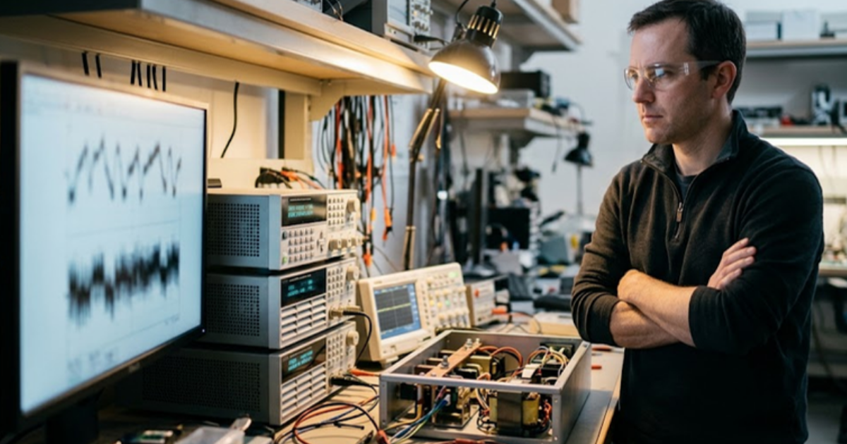
Replaying a recorded AI load profile against the shelf’s control code shows you how the design behaves on the workload it’ll actually power. Standard load steps on a bench prove a module meets its specification. A replayed profile proves the rack stays up.
There’s a discipline to this that’s easy to skip when schedules are tight. Capture a power trace from a running cluster, scale it to the rack you’re building, and run it against the controller with the converter modelled at switching detail. Then alter one thing at a time. Add capacitance, retune a loop, move a threshold, and watch the bus voltage.
“Efficiency still counts, but a rack that trips during a checkpoint has an efficiency of zero for that hour.”
Shelf design has always rewarded engineers who test the awkward cases, and AI racks have simply made the awkward case the normal one. Efficiency still counts, but a rack that trips during a checkpoint has an efficiency of zero for that hour. OPAL-RT builds its simulators for that kind of work, where converter design and data centre stability are treated as one problem. Get the transient right and the efficiency you paid for will show up in service.
Simulation
10 / 28 / 2026
How peers troubleshoot HIL setups faster in a forum
A practical look at how searchable peer threads shorten HIL debugging, covering recurring fault types, what a good question contains and the limits of forum answers.

Simulation
10 / 27 / 2026
A guide to the OPAL-RT engineering community
An orientation to the OPAL-RT community for new members, covering where to ask questions, what to read first, how shared models help, and how to contribute.

Energiesysteme
10 / 24 / 2026
800 VDC power distribution for AI data centers
An explanation of how 800 VDC power distribution carries power from the grid to AI racks, covering conversion stages, DC fault protection and bus stability.