核心要点
- Medium voltage and grid interactive UPS systems are now grid assets as well as protection devices, so their controls carry new engineering risk.
- Most late UPS failures come from controller interactions, which only appear when every controller sees the same grid event.
- A real-time model with the real controllers in the loop turns firmware updates and new grid contracts into routine regression runs.
Medium voltage and grid interactive UPS systems protect data centre load and support the utility at once, but only if transfer timing, control logic and grid behaviour are proven before commissioning.
Data centre electricity use rose 17% in 2025 and is on track to double by 2030, which pushes operators toward larger feeds, higher voltages and power systems that do more than ride through an outage. A UPS sitting on a 13.8 kV or 34.5 kV bus is now a grid asset as much as a protection device, and that dual role is where most of the engineering risk sits.
The teams that get these systems right treat the UPS controller, the static transfer switch and the utility interface as one closed loop. You can’t commission that loop safely on a live campus, so the decisive work happens on a model of it long before the switchgear arrives.
What a medium voltage UPS does for a data centre
A medium voltage UPS conditions and backs up power at distribution voltage, usually between 4.16 kV and 34.5 kV, instead of at the 480 V rack level. It protects an entire hall or building from one point, cuts conductor losses and copper weight, and gives the facility a single place to manage ride-through and transfer.
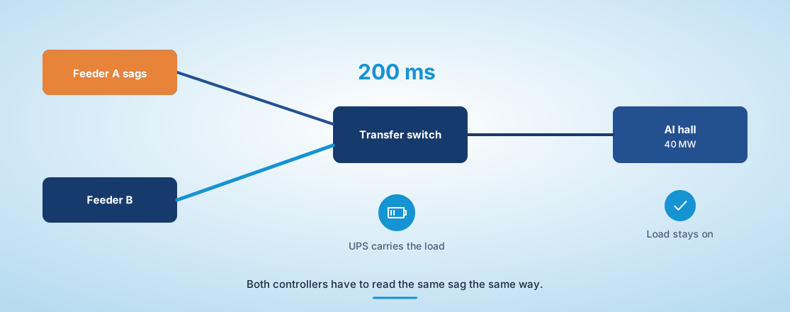
Consider a 40 MW AI hall fed from two utility feeders. A low voltage design needs dozens of 1 MW UPS blocks, each with its own batteries, breakers and controls to coordinate. A medium voltage design places a few large converters upstream of the transformers, so a sag on one feeder is handled once instead of forty times. That simplification is real, but it concentrates consequence. A control fault in one medium voltage unit now affects the whole hall, which is why the controller deserves the scrutiny you would give a protection relay.
How a grid interactive UPS supports the utility while protecting load
A grid interactive UPS uses its inverter and battery to exchange power with the utility during normal operation. It can provide frequency response, peak shaving or peak charge reduction while keeping enough stored energy reserved to carry the critical load through an outage.
The tension shows up in the control priorities. When grid frequency drops, the utility wants the UPS to inject power immediately. If the same event is the start of a fault, the facility wants that energy held for ride-through. The controller has to resolve both requests in milliseconds, using a state of charge floor that never compromises the critical load.
Getting that floor wrong in either direction isn’t cheap. Set it too high and the grid services contract earns little. Set it too low and a long sag after a frequency event can leave the hall short of runtime. Proving the logic means running it through thousands of overlapping grid events, which a test bench can do in an afternoon and a live site shouldn’t attempt.
“A facility that sells frequency response is making a promise to the utility and to its tenants at the same moment, and both promises depend on control logic nobody can watch in real time.”
Where the static transfer switch decides the outcome of a fault
A static transfer switch moves load between two sources using thyristors instead of mechanical contacts, typically within a quarter cycle. In a medium voltage design it decides which source carries the load at the exact moment of disturbance, so its sensing thresholds and timing decide how cleanly the servers ride through.
The hard cases are the ones between clean outages. A high impedance fault on one feeder can pull voltage down slowly, sitting just above the transfer threshold while the UPS starts discharging. If the switch and the UPS controller interpret the same waveform differently, you get a transfer onto a source that is also sagging, or a UPS that discharges into a fault it should have isolated.
Those interactions only appear when both controllers see the same simulated waveform at the same time. Testing the switch alone against a programmable source proves the thyristors work. It says little about how the switch and the UPS behave as one system during the 200 milliseconds that matter.
That’s why the transfer logic belongs in the same test as the UPS controller. A threshold that looks conservative on its own can be the one that hands a sagging source to the load.
Why modular UPS designs change the validation workload
Modular UPS systems parallel many smaller power modules so capacity can grow with the IT load and a failed module can be swapped without an outage. The trade-off is coordination, and it’s significant, because load sharing, circulating current and module dropout logic now have to work across every combination of installed modules.
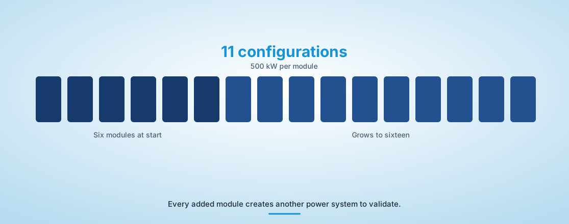
A hall that starts with six 500 kW modules and grows to sixteen has, in practice, eleven different power systems over its life. The validation plan has to cover each configuration, plus the transitions between them. HIL makes that tractable, since adding a module to the model is a parameter change instead of a crane lift.
“Testing the switch alone against a programmable source proves the thyristors work.”
Testing transfer timing before the first module ships
Transfer timing is tested most reliably when the real UPS and static transfer switch controllers run against a real-time model of the feeders, transformers and load. The controllers see voltages and currents that behave like the site, while the test team controls every fault, sag and frequency event.
U.S. data centres already used about 4.4% of national electricity in 2023 and are projected to reach 6.7% to 12% by 2028, so utilities are writing interconnection requirements that ask for proof of ride-through and grid support behaviour. Engineers working with OPAL-RT simulators run those requirement scenarios as automated scripts, so each firmware release is checked against the same fault library before it reaches the site.
The table below summarizes where each test approach earns its place.
| 测试方法 | 这充分证明了 | Where it falls short |
| Factory acceptance on a load bank | Power stages carry rated current and thermal limits hold under steady load | Grid events and controller interaction are absent from a resistive load |
| Programmable AC source testing | Individual devices respond correctly to defined sags and frequency steps | Each device is tested alone, so cross-controller timing is never exercised |
| 控制器硬件在环 | Real UPS and transfer switch controllers react to the same simulated fault at once | Power stage thermal behaviour is modelled instead of measured |
| 电力硬件在环 | A physical module exchanges real power with a simulated grid and site | Rated power is limited by the amplifier, so full hall scale is not reachable |
| Site commissioning tests | The installed system meets its contract on the actual feeders | Fault cases are limited because the load and the utility are both live |
Common failure modes found late in UPS commissioning
Most late failures in medium voltage UPS projects come from interactions between controllers, and the hardware itself is rarely at fault. They surface during commissioning because that’s often the first time every controller sees the same grid at once, which is also the most expensive time to discover them. Several patterns recur across projects.
- Transfer switch and UPS thresholds that overlap during slow voltage sags
- Grid support commands that drain reserve energy below the ride-through floor
- Circulating current between parallel modules after a module is added
- Generator start signals that conflict with UPS battery recharge logic
- Protection relays that trip on inverter fault current shapes they were never set for
Each of these can be reproduced on a model with the real controllers in the loop. On site, reproducing them means faulting a feeder that serves live servers, which no operator will approve twice.
What disciplined validation buys a facility over its service life
Disciplined validation turns a medium voltage UPS from a one-time commissioning risk into a system you can change with confidence. Every firmware update, module addition and new grid services contract becomes a regression run against a known fault library instead of a fresh exposure on the live site.
That matters more as data centres take on grid roles. A facility that sells frequency response is making a promise to the utility and to its tenants at the same moment, and both promises depend on control logic nobody can watch in real time. Teams that keep a validated model of their power system can answer what happens if a question before it becomes an incident report.
We see the strongest programs build that model early and keep it current for the life of the building. With OPAL-RT real-time simulation in the loop, the UPS that protects the load and the UPS that supports the grid are proven to be the same reliable system.

电力系统
11 / 13 / 2026
Grid forming inverters, how they work and how to test them
A technical explainer on how grid forming inverters and their control loops work, and how to test grid forming control through faults, islanding and weak grids.

汽车
11 / 08 / 2026
Active vs passive cell balancing and how to validate balancing logic before pack build
A comparison of active and passive cell balancing in battery packs and a practical guide to validating balancing logic on HIL before pack build.

电力电子
11 / 01 / 2026
Why high frequency SiC and GaN converters outrun real-time simulation
A perspective on why high frequency SiC and GaN converters outrun classic real-time solvers and what engineers now need to validate them as designed.