
You want to test power equipment against the toughest conditions without risking a single asset. Power Hardware-in-the-Loop (PHIL) brings a controlled power interface between a real-time simulation and your physical device, so you can prove control and protection before field exposure. The method connects voltage and current to the device under test while the rest of the system runs as a high-fidelity digital twin on dedicated hardware. Teams in energy, automotive, aerospace, and academia use this approach to shorten cycles, catch faults early, and raise confidence in every build.
The payoff is simple, consistent test coverage at power, repeatable corner cases, and faster iteration. You can stage abnormal grid events, sudden load steps, and thermal stress, all while keeping people and assets safe. You can also reuse the same models across Hardware-in-the-loop (HIL) and PHIL, which keeps controls and plant assumptions aligned across phases. You gain a safer path to prove control strategies, validate power stages, and sign off with clear evidence.
Understand what power hardware in the loop testing delivers
Power hardware-in-the-loop testing sits within Hardware-in-the-loop (HIL), but it exchanges actual power with the device under test.
A real-time simulator computes the rest of the plant, such as a grid or traction drive, and a power interface reproduces the required voltages and currents for the physical hardware. The phrase power hardware in the loop covers this closed-loop setup, where sensors, amplifiers, and interface algorithms complete a bidirectional energy path. That arrangement lets you stress control code and power stages with realistic impedances, time constants, and fault dynamics, without waiting for a full prototype.
Compared with signal-level HIL, PHIL exposes errors that only show up when silicon, magnetics, and thermal limits interact. You can confirm stability margins at the operating point, observe saturation or dead time effects, and test protection logic during faults. Because the digital plant can be reconfigured in minutes, you can sweep operating scenarios across seasons, regions, and duty cycles. The result is clearer coverage, less guesswork during commissioning, and a reliable handoff to field trials.
See how power hardware in the loop supports safer testing
PHIL separates people from uncontrolled energy while still exercising the full control loop at power. Current limits, overvoltage traps, and interlocks sit between the simulator and the device, so a control bug or wiring error stays contained. Engineers can stage severe faults such as short circuits, weak-grid conditions, and phase imbalance, then watch protections act while the amplifier keeps values within safe bounds. The facility footprint stays modest, yet the test envelope includes events that would be risky, impractical, or blocked by site policies.
Repeatable scenarios also lift safety practice. Operators follow a scripted sequence, data logs capture each limit event, and root causes become clear without speculation. Training improves because the same rare events can be replayed for new staff, including orderly shutdowns and recovery steps. These gains arrive without exposing teams to high-voltage yards, busy test tracks, or flight-line constraints.
Explore where power hardware in the loop testing applies
PHIL adds value when your hardware depends on a larger electrical context that is costly to replicate. A digital plant captures that context with the fidelity needed for controls, protection, and energy flows. The approach shines when you care about interactions across converters, sources, and loads that move with time. Teams across energy, automotive, aerospace, and academia put this method to work because it covers power behaviour that benchtop fixtures cannot match.
- Grid-tied inverter and microgrid controller testing: Engineers validate anti-islanding logic, ride-through capability, and phase-locked loop tuning against changing grid strength. Faults, harmonics, and line switching events are staged while the power interface keeps currents within safe limits.
- Battery energy storage system converters: Charging, discharging, and state-of-charge limits are exercised under variable grid or vehicle duty cycles. You can study thermal headroom, current ripple, and protection timing without connecting to a full-scale site.
- Protection and fault management for distribution equipment: Relay curves, current transformer saturation, and breaker coordination are assessed with precise control over fault inception angle and duration. Crews confirm clearing times and misoperation risks under weak-source and high-impedance cases.
- EV traction inverter and e-axle development: Motor emulation and grid emulation pair with the physical inverter to validate torque response, field weakening, and fault ride-through. Repeatable acceleration, grade, and regen events support calibration before track access.
- Onboard chargers and DC fast charging equipment: Compliance, interoperability, and abnormal conditions are tested across grid quality, cable drops, and vehicle-side behaviours. Teams measure efficiency maps and protective trips at power without a full charging plaza.
- More-electric aircraft power conversion and actuation: Power converters, starter-generators, and electromechanical actuators are exercised under load profiles that reflect altitude and temperature effects. Engineers verify fault containment and safe reversion modes while staying inside lab limits.
- Academic power electronics and systems curriculum: Students gain safe exposure to converter control, protection, and measurement at meaningful power levels. Faculty reuse the same bench across labs and research, building skill and evidence that support grants and publications.
Each case benefits from realistic impedance, controllable faults, and measurement at power. The simulator stands in for costly facilities, which keeps schedules relaxed and approvals simple. Hardware can be exercised through scaled power or full power, then correlated with field data to prove credibility. PHIL therefore closes gaps between modelling, bench validation, and acceptance testing with a single, repeatable method.
How power hardware in the loop reduces validation cost

PHIL lowers spend by shrinking the number of physical builds you need before design freeze. Early runs focus on control logic and protection under a simulated plant, so mechanics, cooling plates, and complex fixtures can follow after risk drops. Field trips for grid studies, charger trials, or airport access shift to a lab schedule with stable rates. Energy use falls because you can scale power levels, compress time, and recycle tests without waiting for site windows.
The same lab setup supports multiple projects across the year, which spreads capital outlay and staff time. Libraries of digital plants, test scripts, and reports grow with use, and the best patterns carry forward without rewiring. Integration with configuration control keeps models, firmware, and results aligned, slashing rework during audits. When managers look at the cost per defect removed, PHIL routinely pushes that value down while raising coverage.
Essential components for power hardware in the loop setups
A stable PHIL bench rests on a few building blocks that work as one system. Each element matters because the loop must exchange energy, maintain timing, and protect equipment. Small mismatches in bandwidth, delay, or scaling can tilt stability and distort results. Clear requirements for ratings, accuracy, and timing create predictable behaviour from the first power-up.
Real-time simulator and solvers
The real-time simulator hosts the digital plant and runs it with a fixed time step small enough to capture switching and control dynamics. CPU and FPGA resources share tasks so fast paths, such as electrical subnetworks, stay within tight deadlines. Deterministic scheduling, low jitter, and precise timestamping protect the loop from numerical drift. Model partitioning and I/O mapping should reflect signal paths, cable runs, and device latencies.
Solver choice affects stability and fidelity. Discrete solvers with appropriate damping preserve passivity while avoiding artificial energy injection. Step size, quantisation, and PWM carrier modelling must reflect the device and interface bandwidth. Careful calibration of numerical parameters simplifies correlation against bench measurements.
Power interface and amplifier stage
The power interface converts simulator commands into real voltages and currents for the device under test. Four-quadrant operation, sufficient slew rate, and current limit controls keep the loop safe and accurate. Amplifier bandwidth should exceed the highest control and plant frequencies of interest with comfortable margin. Protective trips, crowbars, and thermal monitoring guard against abnormal events.
Topology choice matters as well. Voltage-source, current-source, or hybrid modes change stability and measurement requirements. Output filters, damping networks, and cabling must be designed with proper impedance so the interface algorithm remains valid. Clear procedures for start-up, shutdown, and faults prevent stress on the device under test.
Sensing, isolation, and measurement
Accurate sensors link the physical device back to the simulator. Voltage dividers, current shunts, or transducers should include isolation suited to the expected common-mode and fault levels. Signal conditioning requires careful attention to bandwidth, noise, and offset so that protection thresholds remain trustworthy. Time alignment across channels improves vector calculations, such as power and impedance estimation.
Measurement fidelity affects more than reporting. Poor scaling or drift can weaken closed-loop stability and mislead tuning decisions. Regular calibration, warm-up routines, and reference checks keep data credible across long sessions. Data paths must be shielded, grounded, and routed to avoid interference from switching edges.
Interface algorithms and stability control
Interface algorithms close the energy loop between the simulator and the device. Common strategies include damping impedance, partial circuit duplication, and model-based compensation for delay and measurement effects. The goal is to satisfy passivity, maintain energy balance, and keep phase and gain within safe margins. Parameter choices depend on amplifier bandwidth, cable inductance, and the plant being emulated.
Stability assessment should be a routine step. Frequency response sweeps, time-domain step tests, and fault insertions reveal weak regions that can be addressed before long campaigns. Engineers should document the stability envelope and revisit it when models, ratings, or firmware change. These practices prevent surprises when moving from small-signal checks to full-power trials.
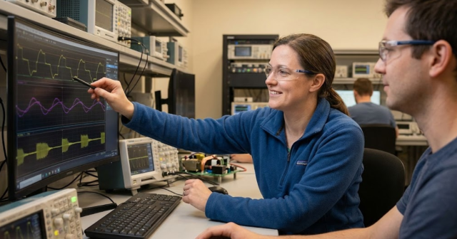
Software orchestration and data management
Test orchestration aligns models, device firmware, safety limits, and data capture. Version control, naming conventions, and scripted procedures reduce errors when multiple teams share the bench. Automated reporting shortens review time and helps leaders sign off with clarity. Access controls and user roles keep the bench safe without slowing work.
Data deserves equal attention. High-rate logs, event markers, and synchronized waveforms support fast root-cause analysis. Storage policies and retention rules should be set so past runs can be compared with new firmware or fresh plant models. Consistent metadata, including calibration and configuration, makes results easier to trust and reuse.
Clear, matched components form a loop that behaves like the intended system without surprises. Each piece contributes latency and bandwidth, so the full chain must be considered when setting targets. The safest approach is to treat ratings, timing, and protection as a single requirement set that applies end to end. That mindset yields benches that produce repeatable, credible evidence at power.
Evaluate performance gains using power hardware in the loop analysis
PHIL compresses weeks of field access into hours of lab time.
Test coverage grows because you can run fault trees, seasonal profiles, and parameter sweeps overnight with no site coordination. Engineers see cause and effect quickly, then adjust code, filters, or protection points on the next run. The pace of discovery picks up, while risk stays contained within pre-set limits.
Quality also improves because the loop exposes interactions that classic benches miss. Thermal, magnetic, and control dynamics meet under realistic voltage, current, and impedance, so defects surface earlier. Repeatable logs support fair comparisons across designs, suppliers, and firmware drops. Managers receive traceable metrics that support decisions on release timing, budgets, and staffing.
Guide your integration of power hardware in the loop testing

Solid integration starts with a clear scope, performance targets, and a shared vocabulary across teams. Power levels, duty cycles, and safety responsibilities should be documented before any hardware arrives. Verification plans should link requirements to test points, data, and acceptance thresholds. Early wins come from a simple loop that grows steadily as confidence builds.
- Set ratings and limits first: Define voltage, current, frequency, and expected fault levels, then select amplifiers, sensors, and cabling that match. Write interlock rules, trip settings, and emergency steps so every operator knows the plan.
- Choose model fidelity on purpose: High-fidelity plants improve confidence, yet they add computation. Start with the behaviours that affect control and protection, then refine where sensitivity warrants it.
- Pick an interface topology that suits the device: Voltage-source, current-source, or hybrid strategies affect loop stability and measurement. Document the choice, its parameters, and the safe operating envelope.
- Calibrate and time-align measurements: Scale factors, offsets, and group delay influence protection, power calculations, and tuning. Create a short calibration routine that runs before each campaign.
- Automate tests and reports: Script setup, stimuli, and pass or fail logic to cut human error. Store logs with configuration and firmware identifiers so results can be repeated months later.
- Correlate against known references: Compare PHIL results with prior benchtop runs or field traces to spot gaps early. Adjust models, delays, or measurement paths until the match sits within agreed tolerances.
- Plan for power scaling: Some work calls for a fraction of full power, while other checks need the nameplate. Use similarity rules for reduced-power testing, then reserve a clear path to full-power proof when needed.
Early alignment prevents noise later in the project. A modest, well-defined loop produces reliable evidence faster than an ambitious bench with unclear rules. Teams that grow capability step by step see fewer resets and hold less idle hardware. Clear ownership, simple scripts, and patient tuning lead to safe, repeatable results.
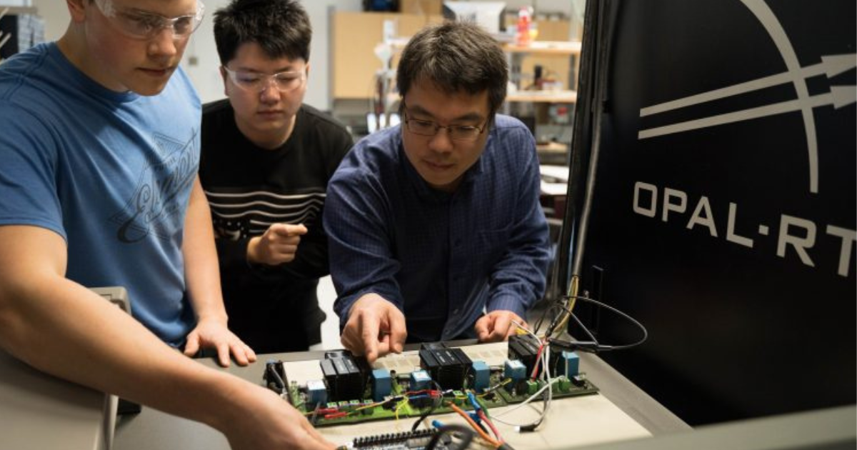
How OPAL-RT supports power hardware in the loop success
OPAL-RT helps engineers in energy, automotive, aerospace, and academia bring PHIL to life with practical tools, proven reference designs, and responsive support. Real-time simulators with CPU and FPGA resources achieve tight time steps, low jitter, and precise I/O timing, which preserves stability and fidelity. Open interfaces connect to common modelling flows, FMU exchange formats, and lab instrumentation, so you can keep your preferred workflow. Built-in libraries for electrical networks, machines, and power electronics shorten setup time, while safety features and passivity aids protect assets during early trials.
Teams also gain value from training, example projects, and configuration templates that map to typical benches, from inverter labs to aircraft power units. Engineers can scale from small benches to higher ratings without rethinking the entire stack, which protects budgets and schedules. Detailed logging, scriptable automation, and correlation tools help you present clear evidence to leaders and reviewers. Choose OPAL-RT for PHIL projects that must deliver speed, accuracy, and trustworthy results.
Common Questions
What is power hardware-in-the-loop testing used for in real-world systems?
Power hardware-in-the-loop (PHIL) testing is used to safely validate how actual power devices behave under complex electrical conditions without exposing them to full-scale field scenarios. It allows engineers to simulate faults, grid events, and load conditions using real-time models connected to real hardware. This approach is widely used in power electronics, microgrids, electric vehicles, aerospace systems, and renewable integration. PHIL testing helps shorten development cycles and improve test confidence. OPAL-RT supports these outcomes through scalable, real-time simulation platforms and proven PHIL setups.
How does PHIL testing differ from traditional HIL simulation?
Traditional hardware-in-the-loop (HIL) testing focuses on signal-level exchanges with control hardware, whereas power hardware-in-the-loop (PHIL) involves actual power transfer to and from the device under test. PHIL introduces amplifiers, sensors, and power interfaces to simulate realistic voltage and current responses. This allows testing of power converters, protection systems, and thermal dynamics in conditions that closely match operational use. OPAL-RT’s real-time simulation systems support both HIL and PHIL, offering flexibility and high-fidelity integration for advanced validation.
Can PHIL help reduce validation and certification costs?
Yes, PHIL significantly lowers validation costs by replacing expensive field trials and large-scale test infrastructure with lab-based simulations. Engineers can validate edge cases, perform root cause analysis, and run fault sequences without building or shipping full systems. This saves budget, time, and resources while still maintaining a high level of test coverage and accuracy. OPAL-RT platforms are designed to provide cost-effective validation at scale, with open architectures that support long-term R&D flexibility.
What equipment do I need to set up a PHIL bench?
A PHIL setup typically requires a real-time digital simulator, a four-quadrant power amplifier, sensing and isolation hardware, interface algorithms, and software for orchestration. Each component must be tightly integrated to maintain loop stability, safety, and fidelity. Depending on your test case, you might also need fault insertion, logging tools, and protection logic. OPAL-RT provides all critical simulation components along with integration support, reducing complexity and setup risks.
How do I know if my project is a good fit for PHIL testing?
PHIL is ideal when your hardware interacts with dynamic electrical conditions that are difficult to replicate on a benchtop or during early prototype stages. Projects involving power converters, grid-connected devices, or control protection logic benefit the most. If you need to test safely under fault conditions, validate timing, or compare firmware releases under changing load conditions, PHIL is likely a strong match. OPAL-RT helps teams assess readiness and scope their PHIL integration efficiently to maximize return.
Real-time solutions across every sector
Explore how OPAL-RT is transforming the world’s most advanced sectors.

Microgrid
11 / 30 / 2025
9 Effective approaches to managing energy in a microgrid
Engineers gain structured guidance on nine proven techniques for microgrid energy management that strengthen microgrid design, testing, and long term reliability.
Power Electronics
11 / 28 / 2025
Power electronics modeling and simulation explained for test engineers
Test engineers get practical guidance on power electronics simulation, converter modeling, and validation workflows that protect hardware and build confidence.
Simulation
11 / 26 / 2025
Real-time testing and simulation for battery energy storage systems
Engineers gain clear guidance on how real-time testing, battery simulation, and BMS testing strengthen safety and reliability in large energy storage systems.
EXata CPS has been specifically designed for real-time performance to allow studies of cyberattacks on power systems through the Communication Network layer of any size and connecting to any number of equipment for HIL and PHIL simulations. This is a discrete event simulation toolkit that considers all the inherent physics-based properties that will affect how the network (either wired or wireless) behaves.