
Key Takeaways
- Treat fault simulation as controlled experiments with fixed starting conditions, pass criteria, and safety limits so results hold up in design reviews.
- Study five complementary faults that cover maximum stress, hard detection, unbalanced behaviour, converter internal failures, and delayed clearing so protection and controls get tested under the conditions that break them.
- Make system disturbance analysis repeatable with scripted triggers, fixed measurement windows, and versioned test cases so model updates produce clear, comparable changes in outcomes.
Fault simulation works when every run has a clear purpose, a known starting state, and measurements you can defend in a design review. Short circuit studies and protection checks often fail because teams jump straight to numbers and skip the conditions that make those numbers valid. You’ll get better results when you treat each fault as a controlled experiment, not a surprise.
“Run five fault scenarios on purpose so protection behaviour stops being guesswork.”
System disturbance analysis also needs repeatability, not just plots. Fault reproduction modelling turns “it happened once” into a test you can rerun after each model update. That’s how you move from interesting waveforms to settings and controls you’ll sign off on.
Define study goals and safety limits before injecting faults
Set the pass criteria first, then choose the fault types and severity that prove it. You should define what must stay within limits, what must trip, and how fast clearing must happen. Safety limits belong in the test plan, not in someone’s memory.
“A fault that exceeds lab or model limits is a failed test setup.”
Start with a short list of outputs that settle arguments quickly, such as peak current, minimum voltage, clearing time, and energy let-through. Lock the pre-fault operating point and the network topology so every run is comparable. Add hard stops for thermal limits, DC bus limits, and maximum current so scripted faults cannot push hardware past safe bounds. Write down assumptions like source strength, grounding method, and sensor scaling, since a “correct” result under the wrong assumptions still misleads your team.
Build a workflow for fault simulation and short circuit studies
Use one workflow for offline fault simulation, short circuit studies, and closed-loop testing so results stay consistent. You’ll get fewer surprises when the same fault definitions, time steps, and measurement windows follow each model version. Teams should treat faults as parameterized test cases, not one-off events. A shared workflow also makes reviews faster and less personal.
- Freeze the base case operating point and topology
- Define fault location, type, impedance, and duration
- Run a baseline to confirm steady measurements
- Inject the fault and log key channels
- Compare against limits and record the outcome
Keep the same test case library across simulation modes so plots match when hardware enters the loop. Hardware-in-the-loop setups benefit from the same discipline because the controller sees identical triggers each time. OPAL-RT is often used in labs to run these scripted cases in real time with strict timing, which helps teams isolate control issues from modelling noise. That approach also makes it easier to rerun the exact case after any parameter change.
5 fault scenarios engineers should study in every program
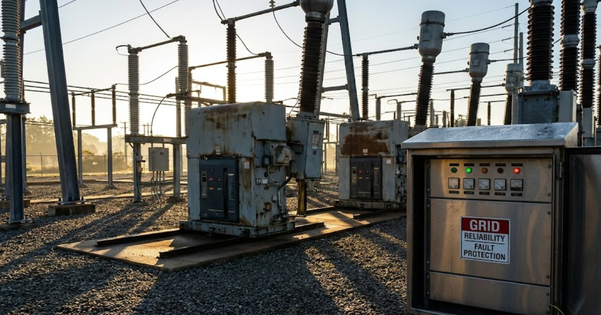
These five scenarios cover the failure modes that most often break protection coordination, expose control instability, or invalidate short circuit assumptions. Each one forces a different combination of high current, low voltage, unbalance, or delayed clearing. Studying all five prevents a plan that only tests “worst current” and misses “hard to detect.” The goal is coverage, not perfection.
1. Three-phase short circuit at the point of connection
This scenario sets the upper bound for current and mechanical duty, so it anchors your protection and equipment checks. It tests breaker interrupting duty, busbar stresses, and how fast voltage collapses at the interface. Models also get exposed here because source impedance, transformer leakage, and current limiting logic strongly shape the peak. Pay attention to the first cycle current and the time to clearing, not just the steady fault current value. If inverter-based resources are part of the system, confirm how their current limiting changes relay reach and pickup margins. Treat this case as the baseline for “maximum severity,” then use it to sanity-check the rest of your fault library.
2. Single line to ground fault with high impedance return
High-impedance ground faults create the most debate because current can look “small” while risk stays high. This case challenges sensitive ground protection, residual measurements, and the assumed neutral grounding method. It also tests your measurement chain, since a little sensor offset can hide the only signal you have. Confirm which elements are supposed to detect the fault, which ones must restrain, and how the system behaves if the fault lingers. Check neutral shift, touch voltage risk, and any control modes that react to voltage unbalance. If the model uses ideal grounding, add the realistic return path assumptions or the study will overpromise detection performance.
3. Phase to phase fault on feeders with unbalanced loading
A phase-to-phase fault stresses negative-sequence behaviour and exposes protection gaps that a balanced three-phase case will never show. It forces you to evaluate how voltage unbalance affects motors, converters, and protection elements that rely on sequence components. Coordination gets tricky on feeders because load unbalance shifts prefault current, which shifts overcurrent margins and directional polarization. Watch for unexpected tripping of adjacent feeders when negative-sequence quantities rise quickly. This case also tests how well your model captures asymmetry in line impedances and load distribution. If the system includes distance or directional elements, confirm the polarization method stays stable during unbalance instead of “hunting” or flipping direction.
4. Converter bridge fault causing DC link overcurrent and collapse
A converter bridge fault is less about grid current magnitude and more about how quickly internal energy moves to the wrong place. It tests the coordination between fast hardware protection, control blocking, and any DC link discharge path. You should confirm what the converter does first, which signals trigger shutdown, and what happens to DC voltage during and after the event. This scenario also reveals if your fault model represents semiconductor behaviour well enough to trust timing and peak stress. Pay attention to interactions between AC-side protection and converter self-protection, since a slow grid trip can leave the converter managing a fault alone. The most useful output is a timeline of trigger, block, current peak, and voltage recovery, since that sequence determines damage risk.
5. Breaker or relay failure leading to delayed fault clearing
Delayed clearing turns a manageable fault into a system-wide disturbance, so it’s the scenario that validates backup protection and coordination discipline. It tests breaker failure logic, time-delayed backup trips, and the selectivity that keeps outages contained. You should verify that upstream elements trip for the right reason and that downstream devices do not misinterpret the delay as a different fault type. This case is also where communications assumptions show up, since delayed signals and permissive schemes can alter clearing time. Focus on what stays stable during the delay, including voltage recovery after clearing and control re-entry behavior. If your plan skips this scenario, the protection scheme will look great on paper and disappoint during an actual misoperation.
| Fault scenario | What you confirm during testing |
|---|---|
| 1 Three-phase short circuit at the point of connection | The highest stress case matches breaker duty and relay timing assumptions. |
| 2 Single line to ground fault with high impedance return | Sensitive ground detection works without false trips from noise or offsets. |
| 3 Phase to phase fault on feeders with unbalanced loading | Unbalance does not break directional logic or coordination margins. |
| 4 Converter bridge fault causing DC link overcurrent and collapse | Internal protection and control blocking limit energy before DC collapse spreads. |
| 5 Breaker or relay failure leading to delayed fault clearing | Backup clearing isolates the fault without cascading trips or instability. |
Reproduce system disturbances with repeatable triggers and measurements

Disturbance reproduction works when your triggers, initial conditions, and measurement windows are fixed and documented. You should script faults so the start time, clearing logic, and reset behaviour are identical across runs. The measurements need a defined pre-fault window and a post-fault window so comparisons are fair. Repeatability matters more than a perfect-looking waveform.
A practical fault reproduction modeling pattern uses an event script that applies a 150 ms single line to ground fault at a defined bus, sets fault resistance to 10 ohms, then issues a breaker open at 200 ms and recloses at 1.0 s. Record the same channels every time, including three-phase voltages and currents, sequence components, breaker status, and any controller trip flags. Keep sampling rates and filters fixed so changes in results reflect system behaviour, not logging differences. Store each run with model version, parameter set, and pass fail notes so system disturbance analysis stays auditable.
Choose test order using risk impact and model confidence
Test order should reflect what can break equipment, trip customers, or invalidate protection margins first. Start with the faults that set hard limits, then move to the faults that are hard to detect. Push lower-risk permutations later, after the model has earned trust. That sequencing keeps schedules honest and avoids spending days on fine tuning before basic behaviour is correct.
High-current interface faults usually come first, then ground faults with weak signatures, then unbalanced faults that stress sequence logic, and finally delayed-clearing cases that validate backups. Each step should reuse the same fault definitions so only one variable changes at a time. When results look wrong, treat it as a modelling confidence issue before treating it as a protection design issue, since both can look identical on a plot. Teams using OPAL-RT in closed-loop validation often keep this same order because it limits risk when hardware enters the loop. Discipline here pays off later, since a fault library built with clear priorities will keep producing usable answers across the full program lifecycle.
Real-time solutions across every sector
Explore how OPAL-RT is transforming the world’s most advanced sectors.

Industry applications, Simulation
03 / 31 / 2026
Managing high-frequency switching in real-time EMT simulation
Precision in testing complex power systems is essential to avoid failures, accelerate innovation, and integrate new technologies safely.

Simulation
03 / 30 / 2026
Understanding timestep requirements for modern power converters
Practical criteria for selecting EMT and real time simulation timesteps for power converters, covering switching resolution, control and PWM timing alignment, multirate approaches, and verification checks.

Energy, Industry applications, Simulation
03 / 29 / 2026
Validating data center energy management systems using real-time HIL
This piece explains how AI workload variability affects data centre power stability and how closed-loop HIL testing helps validate EMS control behaviour under site and grid stress.
EXata CPS has been specifically designed for real-time performance to allow studies of cyberattacks on power systems through the Communication Network layer of any size and connecting to any number of equipment for HIL and PHIL simulations. This is a discrete event simulation toolkit that considers all the inherent physics-based properties that will affect how the network (either wired or wireless) behaves.