Key Takeaways
- Define each interface as a testable contract with measurable limits for timing, data meaning, and physical signalling.
- Use staged integration loops and HIL to validate protocol behaviour and fault recovery before full hardware integration.
- Prioritize observability with synchronized traces, timing analysis, and assertions to reduce late rework and speed root-cause isolation.
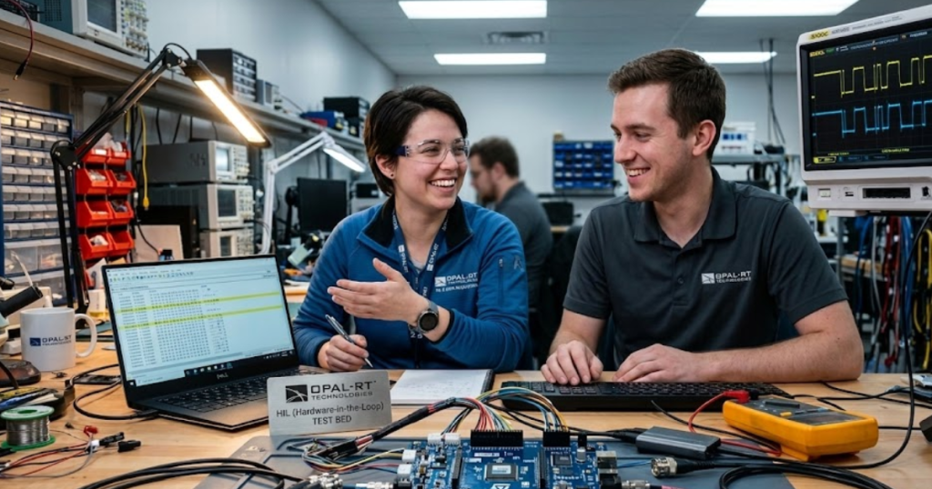
Good firmware integration testing proves your interfaces will work before hardware is fully integrated.
“Most interface failures are not logic bugs, they’re mismatches in timing, framing, electrical assumptions, or state handling across two sides that were built and tested separately.”
Fixing those late is expensive because you’re debugging on a bench with limited visibility, partial tooling, and schedule pressure. Inadequate software testing has been estimated to cost the U.S. economy about $59.5 billion per year, largely from defect-related rework and delays. Integration testing between firmware and physical interfaces is one of the most direct ways to pull that cost forward into a controlled lab setup.
The strongest teams treat interface integration as a measurable contract, not a late-phase “plug it in and see” activity. That contract covers data meaning, timing guarantees, error handling, and physical layer limits, and it gets exercised in staged loops that grow from simulated I/O to hardware-in-the-loop (HIL) and then to full system integration testing. You’ll get better outcomes when you prioritize observability and determinism over test volume, and when you design tests around the failure modes that actually happen on buses and pins.
Firmware integration testing targets timing, data, and electrical boundaries
Firmware integration testing should focus on three boundaries that unit tests rarely stress: timing behaviour, data interpretation, and electrical or physical signalling assumptions. Your goal is to prove the firmware can exchange valid messages at the right cadence, survive invalid traffic, and recover from line-level faults without deadlocks. That means checking not only “did it work” but also “did it meet deadlines” and “did it fail safely.”
A practical way to keep this work scoped is to define interface pass criteria that are observable on a bench. You can measure message period jitter, worst-case response time, queue depth, and error counters, and you can tie each metric to an explicit requirement. You also need to test state transitions, since most integration defects appear when the interface is exercised across reset, sleep, bus-off recovery, or power brownouts. These checks stay relevant even when the application logic changes, because they validate the contract at the boundary.
Electrical and physical boundaries still matter, even when you’re “just testing firmware.” Noise, termination, line biasing, and transceiver behaviour can turn a clean protocol implementation into a field issue, especially once bus load rises. Your integration plan should treat the physical layer as part of the interface, so you can separate protocol defects from signal integrity and wiring problems early, while you still have time to adjust hardware assumptions or firmware tolerances.
Unit testing vs integration testing vs system integration testing
The main difference between unit testing, integration testing, and system integration testing is the failure surface they expose. Unit tests isolate a function or module and validate logic in a controlled setup. Integration testing validates that modules and interfaces exchange data correctly under timing and error conditions. System integration testing validates the complete assembled system behaviour against end goals and safety constraints.
Executives often hear “more testing” and assume it is interchangeable effort, but these layers pay off in different ways. Unit tests reduce regressions and make refactoring safer, yet they rarely catch wiring assumptions, scheduling conflicts, or protocol edge cases. Integration testing is where physical interfaces start to matter, because timing, buffering, and concurrency show up as measurable failures. System integration testing then confirms that the integrated system meets user-visible and certification-level outcomes, but it’s the most expensive place to find interface defects.
| Testing focus | Primary question you answer | Failure types it surfaces most often |
| Unit testing | Does one module produce the correct outputs for given inputs? | Logic errors, boundary conditions, regressions from code changes |
| Integration testing | Do modules exchange valid data under realistic timing? | Timing jitter, race conditions, serialization and parsing mismatches |
| Hardware software integration testing | Does firmware behave correctly with physical signalling limits? | Driver issues, interrupt timing, transceiver and pin-level assumptions |
| System integration testing | Does the assembled system meet end-to-end requirements? | Emergent behaviours, mode handling failures, cross-domain interactions |
| HIL-based integration | Can you reproduce edge cases safely and deterministically? | Fault recovery gaps, timing margin shortfalls, weak observability on bench |
Plan hardware software integration tests from interface requirements first
Hardware software integration testing is most effective when you start from interface requirements and derive testable observables, not when you start from code structure. You want each requirement to map to a measurable signal, a timing bound, and a defined response to bad inputs. This approach keeps scope under control and prevents “busywork tests” that look thorough but miss what breaks on hardware.
Start with an interface contract per port or bus. Define message IDs or frames, scaling, endianness, update rates, and allowable latency, plus what happens on missing data, stale data, and invalid checks. Next, define physical assumptions like voltage ranges, pull-ups, termination, and expected line states during reset. Then add scheduling assumptions such as interrupt priorities, DMA usage, and the maximum time a critical task can be blocked.
Once the contract is clear, sequence tests to reduce ambiguity during failures. Validate the physical layer first, then basic communication, then timing margins, then fault handling, and only then high-load or long-duration runs. That sequencing matters because a bus timing fault can masquerade as a parsing bug, and a reset sequencing issue can look like a protocol dropout. A disciplined order shortens debug loops and makes results easier to trust.
“The goal is a repeatable diagnosis, not a one-off fix.”
Test CAN and other protocols using HIL bus simulation
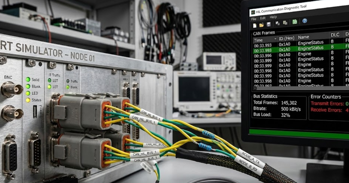
Testing CAN and other communication protocols in HIL should prove that firmware stays correct under load, jitter, and faults while maintaining deterministic timing. A HIL setup can produce repeatable bus traffic, inject errors, and emulate missing nodes without risking physical prototypes. You’ll get the most value when you treat the bus as a controlled stimulus and measure the firmware’s observable reactions, not just its internal logs.
A concrete scenario makes this clear: a controller that publishes a CAN frame every 10 ms can be tested against a simulated network that ramps bus utilization, delays a peer response past the firmware timeout, then forces a bus-off event and recovery. You can verify the firmware’s retry strategy, its diagnostic counters, and the time it takes to resume correct communication, while also checking that application outputs enter a safe state during the dropout. That single setup catches timing, protocol handling, and state-machine issues that unit tests will not see.
HIL is also where cross-protocol interactions become visible. If your firmware bridges CAN to another interface, or prioritizes one bus interrupt over another, you can see starvation and buffer overruns when traffic patterns collide. This is also a good place to set acceptance criteria around jitter and latency, because you can repeat the same run after every change and compare traces directly, without the variability of ad hoc bench setups. OPAL-RT real-time simulators are often used here to keep timing deterministic while the plant and bus traffic run in closed loop.
Choose tools for embedded protocol testing and fault injection
Tools for testing communication protocols in embedded systems should give you three capabilities: controlled stimulus, trustworthy capture, and repeatable fault injection. Stimulus lets you reproduce traffic patterns and timing edges. Capture gives you ground truth for what happened on the wire and on critical pins. Fault injection forces the firmware down paths that normal traffic never triggers, which is where integration bugs hide.
Tool selection should follow the interface contract and your observability gaps, not personal preference. If your team cannot correlate bus traces to firmware timing, prioritize synchronized time stamping and trace export over extra protocol features. If the main risk is recovery from faults, choose tools that can inject errors predictably, rather than relying on noisy cables or “pull the plug” tests. Budget time for calibration and repeatability, since a flaky setup wastes more engineering hours than it saves.
- Bus traffic generation that controls timing, load, and frame content
- Bus capture with accurate time stamps and exportable trace formats
- Pin-level capture for interrupts, chip select, and wake lines
- Fault injection for error frames, dropped frames, and link resets
- Time correlation across firmware logs, traces, and external measurements
Validate embedded interfaces before hardware arrives with staged loops
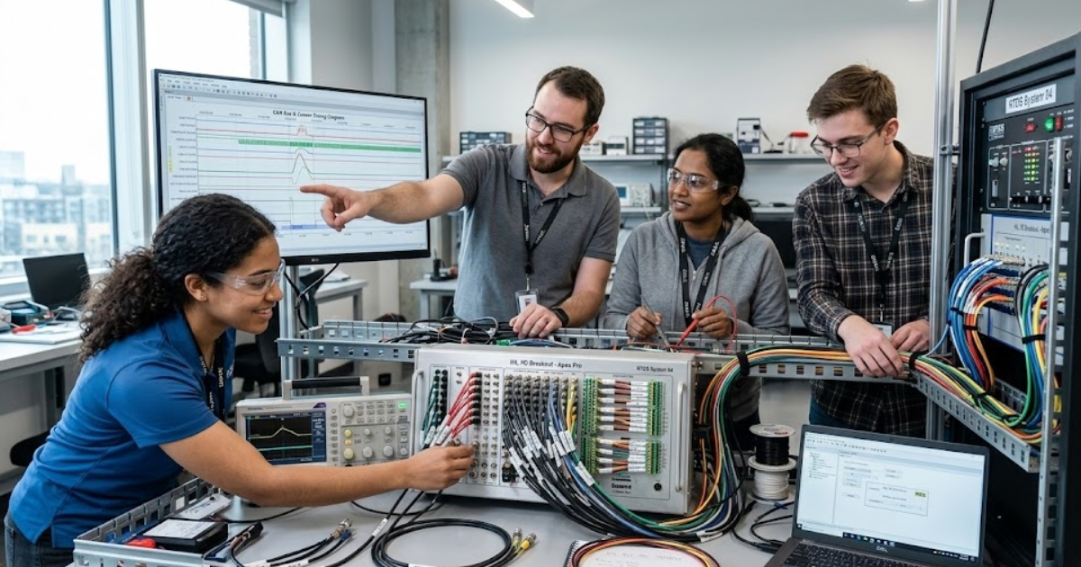
Engineers validate embedded interfaces before hardware integration by moving through staged loops that increase fidelity while keeping control and visibility high. Early loops use simulated peripherals or mocked drivers, later loops use I/O stimulation and bus simulation, and the final loops use actual transceivers and harnesses. The point is not to avoid hardware, it’s to avoid learning basic interface lessons on the most expensive bench day.
Each loop should add one new risk factor at a time. Start with strict parsing and formatting checks, then add timing deadlines, then introduce concurrency and load, and only then introduce noisy physical effects. This keeps failures attributable, which is what you need when the goal is confidence rather than activity. Keep the same pass criteria across loops so the team can see whether risk is shrinking or just shifting.
This staged approach also reduces the gap between software teams and hardware teams. Interface assumptions get surfaced as testable statements early, which prevents “it worked on my setup” disputes later. Better testing infrastructure can eliminate about $22.2 billion of defect-related cost each year through earlier detection and improved tooling. That savings is exactly what staged integration loops are aiming for, at a team scale.
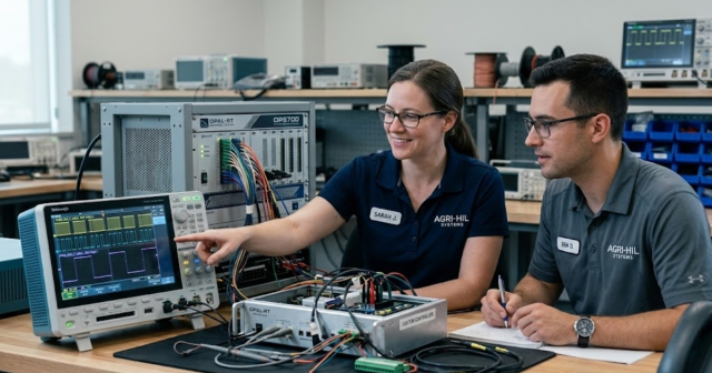
Debug integration failures with traces, timing analysis, and assertions
Debugging integration failures works when you treat traces and timing as first-class data, not as afterthoughts. A good debug loop uses synchronized evidence from the bus, key pins, and firmware events, then tests a narrow hypothesis on the next run. Assertions help you fail fast on contract violations, which shortens the time spent guessing. The goal is a repeatable diagnosis, not a one-off fix.
Start by establishing ground truth at the interface. Confirm the frame on the wire matches the contract, then confirm the firmware receives it within its expected timing window, then confirm the application consumes it. If those steps are out of order, teams often patch the wrong layer and create a new defect. Timing analysis is especially important when symptoms look random, since jitter, interrupt latency, and buffer pressure often sit behind “intermittent” reports.
Good integration testing also changes how teams write firmware. You’ll end up with clearer boundaries, explicit timeouts, and well-defined error states because those are what you can measure and enforce. That’s the lasting payoff: fewer late surprises, and a culture where interface contracts are treated as engineering artifacts. OPAL-RT fits best when you want the same deterministic, traceable setup to stay consistent from early interface checks through HIL and into system integration testing, so results stay comparable as the system matures.
Real-time solutions across every sector
Explore how OPAL-RT is transforming the world’s most advanced sectors.
Industry applications, Simulation
03 / 25 / 2026
Real-time simulation of multilevel converters and cascaded topologies
A practical guide to multilevel converter simulation that explains how cascaded H bridge models are partitioned across CPU and FPGA resources for accurate real-time EMT and hardware in the loop testing.

Simulation
03 / 23 / 2026
Scaling from academic HIL setups to industrial validation platforms
Practical guidance for moving an academic HIL system from an entry level FPGA real time simulator to a modular platform that supports scalable real time simulation, repeatable tests, and traceable industrial validation results.
Industry applications, Power Systems
03 / 22 / 2026
AI workload variability and its impact on data center power stability
This piece explains how AI workload patterns affect data centre power stability and how engineers model and test those effects with converter-aware, real-time methods.
EXata CPS has been specifically designed for real-time performance to allow studies of cyberattacks on power systems through the Communication Network layer of any size and connecting to any number of equipment for HIL and PHIL simulations. This is a discrete event simulation toolkit that considers all the inherent physics-based properties that will affect how the network (either wired or wireless) behaves.