5 Advanced power electronics simulation techniques
Power Electronics, Simulation
01 / 22 / 2026

Key Takeaways
- Model detail should track the measurement you need to trust, not habit.
- Switching, control timing, parasitics, and heat all need their own time scale.
- Repeatable validation comes from locked parameters, reference captures, and rerun tests.
Power electronics simulation stays trustworthy when the model matches risk. Averaged models run fast, but they hide switching stress. Timing errors and ringing slip past them. Better methods will show what the scope will show.
Treat simulation like our test plan with pass-fail limits. We see control models miss reverse recovery. Switching models miss heat drift when temperature is fixed. Pick the method that answers your question, then stop.
Why advanced power electronics simulation techniques matter beyond averaged models
Advanced techniques matter because many failures live in what averaged models smooth out. Switching edges set peak voltage and current stress. Control timing and deadtime set stability margins and distortion. Parasitics steer ringing and EMI, so ignoring them will mislead your design choices.
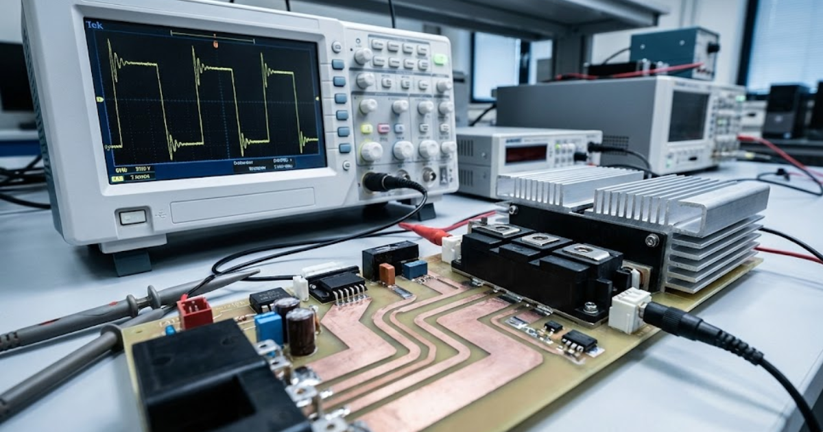
A 100 kHz inverter can look clean on screen, yet a gate-resistor change will trigger tens of MHz ringing on the switch node. That ringing will raise device loss, upset current sharing, and create nuisance trips that feel “random” in the lab. Higher-detail models cost compute time, so treat fidelity as a dial. Use the lowest detail that still reproduces the measurement you care about.
“Use the lowest detail that still reproduces the measurement you care about.”
Five advanced power electronics simulation techniques engineers rely on
These five techniques show up when you need consistent waveform truth, not trends. Each one targets a failure mode basic power electronics simulation misses. Each one costs runtime or setup effort. Pick only what answers the test you care about.
Start coarse, then zoom in where risk is highest. A traction inverter needs different fidelity for loop tuning than for fault timing. Define the measurement first, then set the model detail. That habit keeps modelling effort proportional to value.
1. Sub-microsecond switching models aligned to control loop timing
Sub-microsecond switching models capture dv/dt, di/dt, and capacitances that set peak stress. Time steps in the tens to hundreds of nanoseconds show how sampling and PWM updates line up with edges. Control logic reacts to what it samples, so timing matters. It will also capture diode recovery and snubber behaviour. Runtime rises fast, so use this only where edges decide pass or fail.
A current-mode buck converter is a common trap. Coarse steps hide a brief current spike when a PWM update lands near an edge, so the loop looks stable. Fine steps show the spike pushing the controller into saturation and then recovering. Fixes become concrete: shift sampling, adjust deadtime, or tune the compensator. Use device data close to your operating point.
2. Multi-rate co-simulation separating control, switching, and thermal dynamics
Multi-rate co-simulation splits time scales so fast and slow physics stay accurate. The power stage runs fast around switching, the controller runs at its sample period, and the thermal model runs slower while feeding temperature back into losses. You’ll connect control choices to heat rise without simulating nanoseconds for an hour. You’ll also spot controller rate jitter that shows up as ripple. Clear interface timing rules matter as much as circuit equations.
An EV inverter drive-cycle check fits well here. The controller pushes current across speed and torque, and junction temperature follows with delay. Coupling shows when temperature rise shifts switching loss and forces current limiting. Validate signals at each interface and anchor the model with one steady-state bench capture.
3. FPGA-based real-time simulation for hard switching and fault behaviour
FPGA-based real-time simulation runs the plant at a fixed time step so real controllers and protection hardware can close the loop. Latency and I/O delays become part of the test. That makes it strong for fault timing, gating logic, and sensor conditioning. Offline results look calm, then protection fails when timing is off.
Short-circuit detection on a silicon carbide inverter leg is a clear use case. Inject the fault, run the gate-driver logic, and measure time from desaturation event to gate turn-off. The model will show current rise and clamp behaviour with enough timing detail to judge margin. OPAL-RT real-time simulators are often used for repeatable fault injection when teams want closed-loop tests without risking full-power hardware. Calibrate sensor delays and thresholds so the timing matches your build.

4. Detailed semiconductor loss and thermal coupling models
Electro-thermal loss models link electrical waveforms to junction temperature, then feed temperature back into device behaviour. That loop predicts when a design meets average loss targets but still violates thermal limits during transients. It also reveals uneven heating across phases or paralleled devices. Heat problems rarely announce themselves early during tests.
A three-phase inverter with paralleled modules can share current well at start-up, then drift as one module runs hotter. Higher temperature raises on-resistance, raises loss, and shifts current sharing again. A coupled model will show the slow drift that bench tests often catch late. You’ll also get a better basis for derating logic in control software. Good thermal parameters matter, so tie the model to a few temperature measurements.
5. Fault-focused simulation using non-ideal components and parasitics
Fault-focused simulation adds the non-ideal parts that decide what breaks first. Stray inductance, capacitor ESR, diode recovery, sensor offsets, and wiring resistance set surge currents and overvoltage peaks. Faults stop looking like clean switches and start looking like waveforms. Protection thresholds and clamp sizing become testable. You’ll see how sensor offsets shift trip points during fast current rise.
Opening an input contactor during high current can create a DC-link spike shaped by layout inductance and capacitor ESR. Adding those non-ideal elements will show ringing that hits the bridge and can false-trigger overvoltage logic. You can then size snubbers, clamps, and filters with less guesswork. Data quality is the constraint, so pull parasitics from layout and confirm with an impedance check.
| Technique focus | Why it pays off |
| 1. Sub-microsecond switching models aligned to control loop timing | You’ll see edge stress and timing clashes before bench testing. |
| 2. Multi-rate co-simulation separating control, switching, and thermal dynamics | You’ll link control actions to heat rise without extreme runtimes. |
| 3. FPGA-based real-time simulation for hard switching and fault behaviour | You’ll verify protection timing using real I/O and repeatable faults. |
| 4. Detailed semiconductor loss and thermal coupling models | You’ll catch thermal drift that shifts losses and current sharing. |
| 5. Fault-focused simulation using non-ideal components and parasitics | You’ll set clamps and thresholds using realistic surge waveforms. |
“Lock key parameters, rerun the same tests after each change, and treat mismatches as model bugs until proven otherwise.”
How to choose the right simulation technique for your validation goals
The right technique is the one that reproduces the measurement you need to trust. Start from the waveform, timing margin, or temperature limit that will decide pass or fail. Choose the smallest time step and the fewest non-ideal details that recreate it. That keeps compute and effort proportional to risk.
Match each goal to a bench instrument and you’ll pick faster. Switch-node ringing maps to fine-step switching and parasitics. Protection timing maps to real-time, closed-loop tests where I/O delay is real. Efficiency and derating map to electro-thermal coupling over the operating cycle. Lock key parameters, rerun the same tests after each change, and treat mismatches as model bugs until proven otherwise. OPAL-RT fits when closed-loop timing is the main unknown, and your test definitions still decide the outcome.
Real-time solutions across every sector
Explore how OPAL-RT is transforming the world’s most advanced sectors.

Industry applications, Simulation
03 / 31 / 2026
Managing high-frequency switching in real-time EMT simulation
Precision in testing complex power systems is essential to avoid failures, accelerate innovation, and integrate new technologies safely.

Simulation
03 / 30 / 2026
Understanding timestep requirements for modern power converters
Practical criteria for selecting EMT and real time simulation timesteps for power converters, covering switching resolution, control and PWM timing alignment, multirate approaches, and verification checks.

Energy, Industry applications, Simulation
03 / 29 / 2026
Validating data center energy management systems using real-time HIL
This piece explains how AI workload variability affects data centre power stability and how closed-loop HIL testing helps validate EMS control behaviour under site and grid stress.
EXata CPS has been specifically designed for real-time performance to allow studies of cyberattacks on power systems through the Communication Network layer of any size and connecting to any number of equipment for HIL and PHIL simulations. This is a discrete event simulation toolkit that considers all the inherent physics-based properties that will affect how the network (either wired or wireless) behaves.