8 reasons engineers rely on hardware in the loop systems for power electronics
Simulation
12 / 12 / 2025

Key Takeaways
- Hardware in the loop testing lets you expose controllers to demanding electrical conditions while keeping high-voltage stages in simulation, which reduces risk and extends what you can validate before prototypes arrive.
- Power electronics testing gains structure and repeatability when hardware in the loop is tied to automated scenarios, regression suites, and shared model libraries across teams.
- HIL simulation systems help you tune control strategies, modulation approaches, and protections early, so first hardware power-up sessions focus on refinement rather than basic stability fixes.
- Controller validation against grid disturbances, fault cases, and complex architectures becomes more practical when controllers interact with detailed real-time plant models instead of relying only on limited bench hardware.
- Investing in hardware in the loop infrastructure and disciplined workflows creates a common platform that supports many projects, improves confidence in every firmware release, and strengthens collaboration across engineering groups.
Your power electronics tests only feel reliable when you trust every result, every time. Converter control code, FPGA logic, and protection settings all carry risk long before a power stage reaches the lab. A single wrong assumption in a model or timing parameter can stress silicon, damage equipment, or push schedules off track.
“Hardware-in-the-loop (HIL) testing gives you a way to expose controllers to demanding electrical conditions while keeping high-voltage hardware safely out of the picture.”
Teams working on inverters, converters, motor drives, and grid interfaces now use HIL as a standard part of power electronics testing. Instead of waiting months for full prototypes, you can connect control hardware to a real-time simulation of your converter and grid models and run thousands of scenarios in days. That practice shortens design iterations, improves test coverage, and lets you answer detailed questions from safety, compliance, and system architects with confidence. You gain a clearer view of controller behaviour under difficult conditions, which means fewer surprises when hardware reaches higher power levels.
Hardware in the loop testing supports rigorous power electronics development
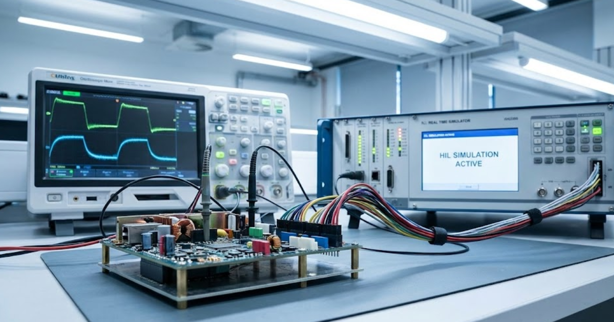
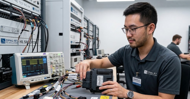
Hardware in the loop testing connects real controller hardware to a high fidelity, real-time simulation of the power stage and grid. The digital simulator runs a model of the converter, machine, or network, updates that model every few microseconds, and exchanges input and output signals with the controller just as a physical plant would. This setup lets you execute closed loop tests where firmware responds to current, voltage, and speed feedback that accurately represent the system you plan to build. Industry references describe HIL as a proven technique for validating embedded control systems and power electronics before building full prototypes, because the controller interacts with a simulated plant under realistic timing and signal conditions.
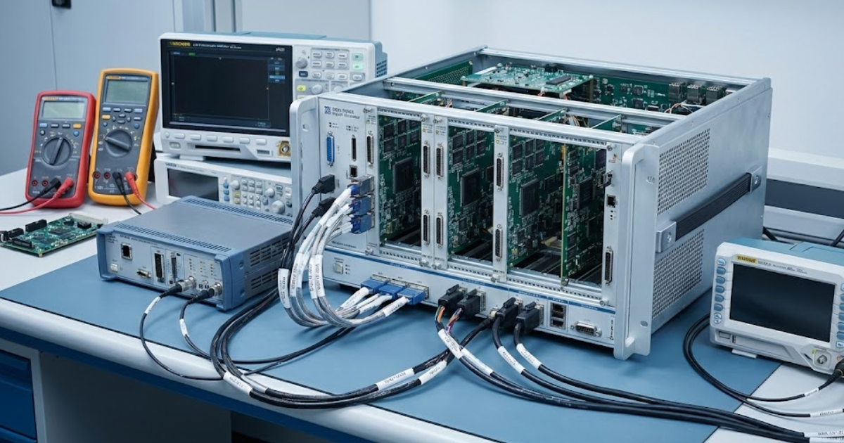
For power electronics development, HIL turns the simulator into a flexible test bench that can represent anything from a single DC DC stage to a multi-converter grid connection. You can start with detailed switching models for waveform-level checks, then move to averaged models for system-level studies without changing the overall test setup. Controller gains, state machine logic, protections, and communications all experience current and voltage conditions that match your design assumptions. As a result, issues such as limit cycling, timing jitter, or missed protections appear early, when firmware and models remain easier to adjust.
The same platform supports long-duration and corner-case scenarios that would be risky, inefficient, or sometimes impossible to reproduce on a physical prototype. Engineers can sweep parameters, replay recorded field data, or execute automated regression suites overnight while keeping staff and hardware safe. Power electronics testing then shifts from manual, ad hoc lab sessions to structured campaigns with clear metrics, traces, and pass or fail criteria. This discipline makes hardware in the loop testing a key method for teams who need rigorous validation of converters that will connect to high-voltage grids, traction drives, and energy storage systems.
8 reasons engineers rely on hardware in the loop systems
Time pressure, strict safety requirements, and tight lab capacity all push power electronics teams to get more value from every test. Hardware in the loop systems appeal because they connect directly to controller hardware and behave like configurable power plants under software control. The same simulator that validates a traction inverter control board today can represent a grid-tied converter or storage interface on the next project. Teams that invest in this approach often point to concrete benefits around control refinement, fault coverage, hardware reuse, and collaboration across engineering disciplines.
| # | Focus area | How hardware in the loop testing helps |
| 1 | Early converter control refinement | Shortens firmware iterations and reveals control issues before hardware build. |
| 2 | Fault behaviour assessment | Lets you inject faults safely and observe closed loop response in detail. |
| 3 | Modulation and switching tuning | Allows consistent comparison of PWM and switching schemes across varied conditions. |
| 4 | Grid disturbance reproduction | Replays sags, swells, and frequency events for controller verification. |
| 5 | Prototype reduction | Replaces some physical builds with virtual prototypes tied to real controllers. |
| 6 | Scenario consistency | Automates repeatable test sequences for stable performance evaluation. |
| 7 | Model and controller correlation | Helps align simulated behaviour with measured controller response. |
| 8 | System-level integration | Connects multiple subsystems inside larger architectures for scalable testing. |
1. Faster refinement of converter control strategies during early stages
Early in a project, control engineers often work from incomplete requirements, shifting plant models, and limited lab access. Hardware in the loop testing lets you plug an actual control board into a simulated converter and start tuning loops long before any power stage is built. You can explore gain schedules, feedforward paths, observers, and state machine timing while the real-time model exposes the controller to realistic currents, voltages, and mechanical dynamics. This approach makes control behaviour visible at a very early point, which avoids surprises when prototype hardware finally arrives.
Because the simulator responds to the controller in microseconds, you can test fast current loops, inner voltage regulation, and outer speed or power loops with confidence that timing interactions are represented accurately. Engineers often connect debuggers, logic analysers, and on-chip tracing tools while the HIL simulation system runs scenarios that would be too aggressive to attempt on a first prototype. Power electronics testing then becomes a software activity during the early stages, which fits well with continuous integration practices and automated builds. Teams that follow this pattern usually reach first lab power-up with stable control strategies, shorter bring-up sessions, and fewer late firmware rewrites.
2. Safer assessment of fault behaviour through controlled closed loop testing
Fault studies carry higher risk than normal operation because they stress IGBTs, MOSFETs, bus capacitors, and magnetic components. With HIL, the converter and grid models absorb this stress numerically, while the controller hardware still experiences all the same measurements, flags, and communications traffic. You can evaluate how firmware reacts to DC-link overvoltage, short circuits, phase loss, sensor failures, or mis-synchronised contactor events without exposing lab hardware to damage. Engineers can slow down, repeat, or slightly modify each event, which helps root cause tricky protection issues that might only appear occasionally on a bench prototype.
Power electronics testing that targets safety approvals benefits strongly from this controlled, repeatable fault setup, because traceability of each scenario matters to assess compliance. Grid codes, functional safety standards, and project-specific requirements often list dozens of fault cases that must be exercised and documented. Hardware in the loop testing lets you script these events, capture waveforms and logs for every run, and maintain a record that survives firmware refactors and hardware revisions. Public case studies show that HIL-based fault campaigns can expose controller weaknesses and protection gaps before field trials, which reduces project risk and unplanned rework.
3. Reliable tuning of modulation and switching methods under varied conditions
Modern converters often switch at tens of kilohertz while tracking complex current or voltage references, so small changes in modulation strategy can have large effects. HIL makes it possible to compare pulse-width modulation schemes, carrier interleaving patterns, and dead-time compensation approaches across many loading and thermal points without reconfiguring lab hardware. Engineers adjust parameters such as switching frequency, filter values, and current limits inside the model, then observe controller behaviour and calculated device stress in response. This method reveals interactions between modulation, control gains, and protection thresholds that are harder to see when a single physical prototype must be rewired for every experiment.
Because the power stage exists in software, you can also explore extreme conditions, such as high grid impedance, unusual machine parameters, or aggressively rated semiconductor devices, without risking damage. Results from these sweeps guide decisions about acceptable switching losses, electromagnetic interference margins, and thermal headroom before committing to hardware layouts. HIL simulation systems support such studies with detailed electromagnetic transient models, fast solvers, and flexible I/O so that controllers see waveforms close to what they will encounter later. These capabilities make modulation and switching choices more informed and more robust, particularly for converters that must cover wide operating ranges or multiple product variants.
4. Precise reproduction of grid disturbances for controller verification
Power grids now contain more converter-based resources, which introduces complex behaviours during voltage sags, frequency deviations, and faults. HIL platforms let you reproduce such disturbances on demand by driving the controller with simulated three-phase waveforms that include harmonics, flicker, and unbalanced conditions. You can validate ride-through algorithms, power factor control, and frequency support functions against a library of scenarios that reflect present and emerging grid codes. Controllers then reach field trials with a documented history of performance under stress, instead of relying mainly on a few manual tests performed on a prototype.
Engineers also use hardware in the loop testing to replay recorded waveforms from transmission or distribution incidents and observe how new converter firmware would respond. That technique supports root cause analysis when events occur in service and provides insight when tuning new control modes such as grid-forming behaviour. HIL simulation systems often integrate with power system study tools, making it straightforward to generate cases that match specific feeders, substations, or microgrids. As a result, grid compliance work feels less like a one-off hurdle and more like an ongoing design input that shapes the controller from early development onward.
“When HIL simulation systems integrate smoothly with the rest of your engineering tools, they stop feeling like side projects and start acting like core infrastructure.”
5. Reduced reliance on physical prototypes during iterative development
Every physical prototype consumes budget, lab space, and technician time, so relying on hardware for every iteration slows projects significantly. With hardware in the loop testing, you can move large parts of converter development into the simulator and treat each new control concept as a software release. Engineers still need hardware at key milestones, yet they meet those milestones with firmware that has already survived extensive HIL campaigns. This shift from hardware-first testing to simulation-led validation reduces scrap, shortens bring-up sessions, and keeps scarce power stages available for the most valuable experiments.
Some teams pair HIL with power hardware-in-the-loop setups so that low-level control matures on a controller-only bench before higher power validation begins. In those cases, the same models, scenarios, and automation scripts support both controller hardware-in-the-loop and later power amplifier based test stages, which keeps effort focused on engineering rather than test rebuilds. Power electronics testing then becomes a continuum, starting from controller code running against pure simulation and progressing toward full power only when needed. This structure aligns well with R&D budgets that must balance new feature work, sustaining projects, and maintenance of existing test infrastructure.
6. Consistent execution of test scenarios for stable performance evaluation
Manual lab work often suffers from inconsistent setups, slight wiring differences, and human variation in how test steps are executed. HIL platforms address that pain by letting you script scenarios, version-control them, and run them automatically as part of scheduled test campaigns. Each run uses the same initial conditions, parameter sets, and timing, which gives you confidence that changes in results truly come from firmware or model modifications. Log files, waveforms, pass or fail flags, and performance metrics then build a history that helps engineering leads track progress and spot regressions early.
Consistent execution matters especially for controllers that must meet strict timing, harmonic, or efficiency targets across a wide range of operating points. Automated HIL scripts can sweep load levels, DC bus voltages, temperatures, and communication delays while collecting the same measurements for each combination. This approach creates a structured data set that supports sensitivity studies and design reviews without asking engineers to repeat manual tests for every small firmware tweak. The end result is a more stable assessment of performance and a clearer story when presenting converter behaviour to system integrators or certification bodies.
7. Better correlation between modelled systems and controller performance
A common concern in simulation-heavy projects is confidence that models actually reflect how the controller and hardware will behave. Hardware in the loop testing closes this gap by placing the controller in the signal chain, forcing it to respond to simulated current, voltage, and speed feedback while engineers compare results with offline studies and, later, physical tests. Discrepancies between expected and measured behaviour often reveal issues such as misinterpreted sensor scaling, timing differences, or overly simplified plant assumptions. Once those differences are understood, teams can refine both the model and the firmware, which improves the predictive value of future simulations.
Power electronics testing workflows that mix offline simulation, HIL, and hardware measurements tend to converge on a consistent representation of the system. Engineers might, for example, identify that a motor model needs extra loss terms or that a grid representation should include specific resonance effects observed on a test feeder. They then validate the updated models using HIL scenarios and confirm that controller behaviour matches what appears on hardware within acceptable margins. This continual alignment effort pays off when new projects start, because existing models and controller code already have a proven track record of matching measured behaviour.
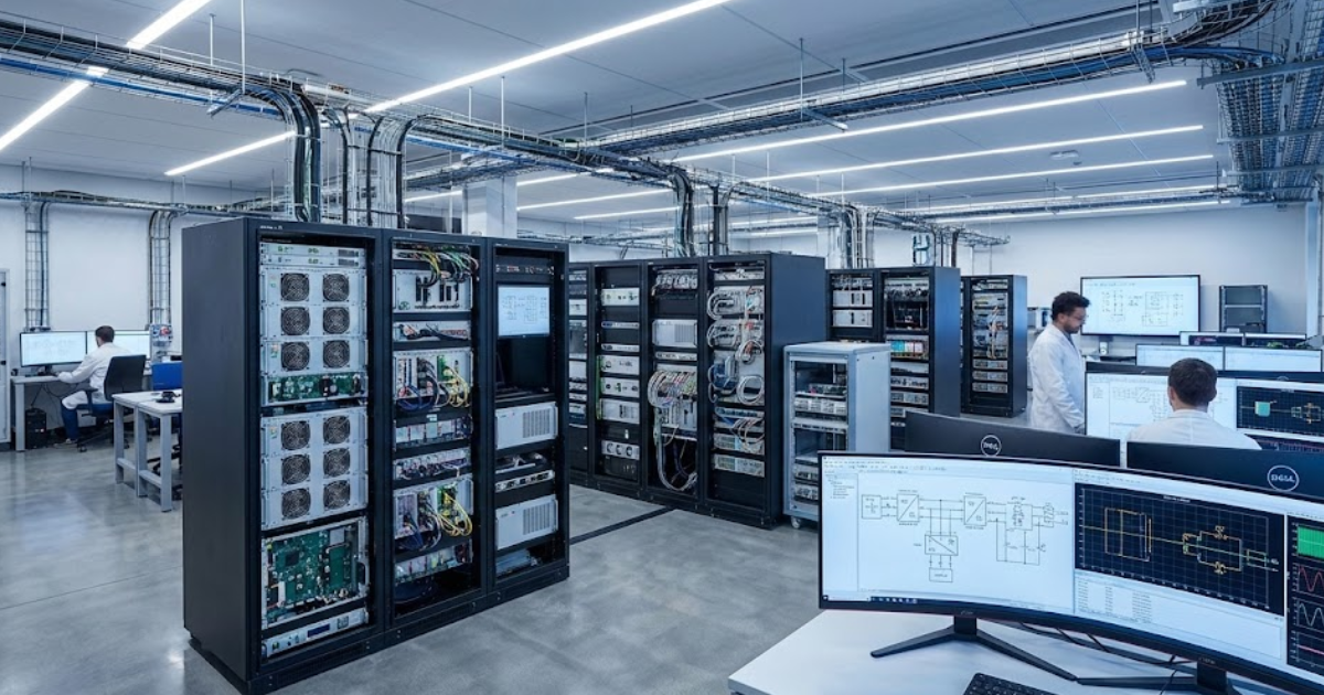
8. Scalable integration of power electronics subsystems within complex architectures
Large projects such as electric vehicles, aircraft power systems, or multi-terminal grids include many converter-based subsystems that interact tightly with one another. HIL platforms allow engineering teams to connect multiple controller boards and plant models into a single testbed so that interactions appear before integration in a full lab or field setup. You can represent traction inverters, DC DC converters, on-board chargers, and grid connections inside one real-time simulator or across several linked units. This approach highlights issues such as shared DC bus stability, communication timing conflicts, or unintended control interactions that might not surface when subsystems are tested alone.
Scalability also matters across time, because projects rarely stop at a single configuration or rating. With modular models and configurable I/O, the same HIL infrastructure can support early concept studies, detailed subsystem work, and later regression testing for software updates across many product variants. System architects gain a clearer picture of how local converter decisions affect higher-level functions, such as energy management, grid support, or vehicle performance. This shared platform helps reduce integration surprises and gives teams a practical way to coordinate work that spans multiple organisations, suppliers, and engineering specialties.
When you look across these patterns, a consistent theme appears around shifting risk and effort away from fragile prototypes and toward controlled simulation. Hardware in the loop systems make it easier to study faults, corner cases, and integration questions that would otherwise consume large amounts of lab time. They also encourage better modelling discipline, tighter collaboration between firmware and system engineers, and clearer evidence for project stakeholders. For organisations building advanced converters and power systems, that combination of safety, speed, and insight often justifies the investment in HIL infrastructure.
How HIL simulation systems strengthen power electronics testing workflows
Hardware in the loop setups deliver the most value when they fit naturally into your everyday development rhythm. Teams gain the strongest benefits when HIL simulation systems connect cleanly with modelling tools, version control, test automation, and lab instruments. That integration turns the simulator from a specialist asset used only for demonstrations into a shared workbench that supports many projects. Several practical practices help your group treat HIL as a routine part of power electronics testing rather than a one-off experiment.
- Reusable scenario libraries and parameter sets: Store grid faults, load profiles, and start-up sequences as named scenarios in your HIL project so that anyone on the team can run them consistently. Parameter sets for converter ratings, filter designs, or machine variants can be kept alongside those scenarios, which turns the simulator into a catalogue of test-ready cases. This organisation prevents individual engineers from maintaining private script collections and reduces the chance of inconsistent assumptions between projects. As new issues arise in the field, you can add corresponding scenarios to the library and apply them to upcoming designs.
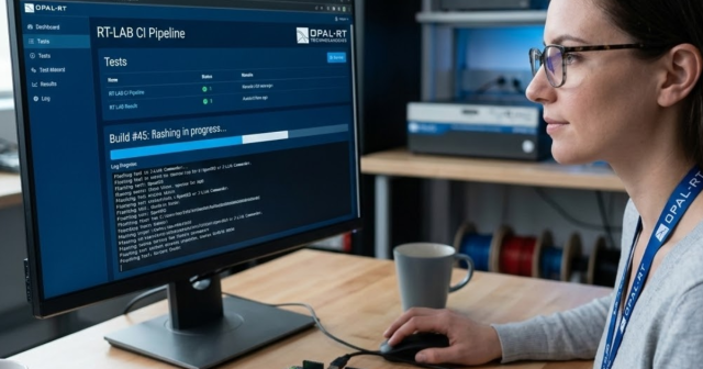
- Continuous integration and regression testing with HIL: Use your existing build and test infrastructure to trigger HIL runs when firmware changes, just as you might already trigger unit tests or static analysis. A pool of simulators can execute key scenarios on each new build or on a scheduled basis and publish simple pass or fail summaries. Engineers then see immediately when a change breaks a requirement related to protection timing, control stability, or efficiency. This habit raises confidence in every software release that reaches the lab and keeps subtle regressions from slipping into field deployments.
- Tight links to modelling and control design tools: HIL simulation systems work best when models flow directly from your preferred tools for converter and grid studies without manual re-entry. Automatic code generation, model export in standard formats, or shared libraries reduce friction when moving from offline studies to real-time execution. Controller engineers then receive plant interfaces that match what they used during desktop simulation, which keeps focus on control logic rather than wiring and scaling. This consistency supports higher quality models and shortens the path from first concept to closed loop tests.
- Harmonised workflows between controller and system engineers: Shared HIL test benches encourage closer collaboration between specialists who focus on firmware and those who focus on system behaviour. System engineers can contribute scenarios that reflect grid studies or vehicle-level cases, while controller engineers focus on meeting stability and performance targets under those conditions. Regular joint reviews around HIL results often uncover assumptions that were never written into requirements documents. That transparency reduces late rework and builds trust across disciplines that previously worked in isolated tools.
- Structured data capture and traceability: Archive waveforms, performance metrics, and configuration files from each HIL campaign so that you can reproduce important results months or years later. Link those artefacts to requirements identifiers or issue tracking tickets to keep a clear chain from problem to test to fix. When certification audits or customer reviews arise, this discipline makes it much easier to show evidence for claims about converter behaviour. It also helps new team members understand past design choices, since they can replay scenarios and review the associated logs.
- Support for both controller HIL and power HIL stages: Some organisations deploy controller-only HIL for firmware validation and separate power hardware-in-the-loop setups for full power tests, yet both can share models and scenarios. Aligning these platforms ensures that a fault case studied at low power appears again when converters reach higher energy levels, which simplifies debugging. Controller teams gain assurance that behaviour seen during early HIL work will remain valid when hardware interacts with amplifiers, machines, or grid simulators. Test labs benefit because they spend less time re-creating support scripts and more time on high-value engineering decisions.
- Interfaces to lab equipment and field data sources: Connecting HIL systems to oscilloscopes, power analysers, or recording hardware makes it straightforward to compare simulated results with measurements taken from prototypes or field units. Engineers can stream recorded data into the simulator to replay unusual events, then adjust control logic until behaviour improves. The same interfaces often help with hardware validation, since triggers and logging setups can match those used during pure simulation runs. This continuity simplifies correlation work and lets teams reuse their measurement knowledge across simulation and hardware phases.
When HIL simulation systems integrate smoothly with the rest of your engineering tools, they stop feeling like side projects and start acting like core infrastructure. Power electronics testing then benefits from repeatable workflows, higher test coverage, and more transparent communication across teams. Engineers waste less time on manual setup work and spend more energy on diagnosing issues, improving controls, and validating fixes. Over time, this steady refinement of process often matters as much as individual test features when measuring the return on a simulator investment.
How OPAL-RT helps teams advance hardware in the loop testing
Engineering teams often approach OPAL-RT when lab benches are overloaded, test queues are long, and critical controller updates still need validation. The company focuses on real-time digital simulators and software that connect directly to controller hardware so that your converters, machines, and power systems can be exercised in closed loop. Customers use these platforms to build detailed models of power electronics and grids, run them at small time steps, and link them to control boards through flexible I/O options. That combination helps reduce reliance on scarce high-power prototypes and makes it practical to run long-duration or high-risk scenarios that would be difficult to attempt in a physical lab. Teams gain practical tools to expose design flaws early, refine control strategies, and keep projects moving even when hardware or lab time is limited.
OPAL-RT also works closely with engineers who need HIL setups to match established modelling workflows, coding standards, and safety processes. Support for popular simulation languages, model import approaches, and automation interfaces helps teams integrate HIL runs into continuous integration systems and lab scheduling tools without reinventing existing practices. Field experience across applications such as vehicle electrification, grid-connected converters, and industrial drives gives the company a practical view of typical pain points, including I/O configuration, deterministic timing, and test coverage. Clients often treat the resulting HIL benches as shared assets that multiple projects can use, which spreads cost while raising confidence in every new converter release. This track record and focus on engineering outcomes give technical leaders a strong basis to trust OPAL-RT as a long-term partner for power electronics testing investments.
Common Questions
How do I choose the best power system simulation software for my project?
Choosing the right tool depends on the type of studies you need, such as electromagnetic transient analysis, steady-state planning, or hardware-in-the-loop validation. You should compare solver methods, model libraries, and integration paths with your existing workflow. Real-time capability and hardware connections are key if your project requires closed-loop testing. OPAL-RT helps you match the right simulation approach with practical lab integration so you can move faster with less risk.
What’s the difference between offline and real-time power system simulators?
Offline simulators run detailed studies without time constraints, which makes them well suited for design and sensitivity analysis. Real-time simulators, on the other hand, execute models within strict time steps to stay synchronized with hardware and controllers. Both approaches often work best when paired, with offline studies guiding scenarios later tested in real time. OPAL-RT bridges this gap by supporting both offline modeling and real-time execution, giving you continuity across design and testing stages.
Why should I use hardware-in-the-loop for power system projects?
Hardware-in-the-loop (HIL) allows you to test controllers, relays, and converters against simulated grids before using live hardware. This approach improves safety, reduces test time, and exposes issues earlier when they are less costly to fix. With accurate models and tight timing, you can validate protections, controls, and fault cases with confidence. OPAL-RT offers purpose-built HIL platforms that give engineers a reliable way to test without putting equipment or schedules at risk.
Can power system modeling and simulation improve collaboration between my teams?
Yes, consistent simulation models serve as a shared reference across design, testing, and planning teams. When everyone works from the same data sets, it reduces duplication, errors, and misalignment between studies. Shared libraries and automation also make it easier to reproduce cases and track changes over time. OPAL-RT supports open standards and scripting so you can integrate across groups while keeping models transparent and traceable.
How can I future-proof my investment in simulation tools?
The most effective way is to choose platforms that are open, scalable, and adaptable to new standards. You want flexibility to run larger networks, add new device models, or connect emerging hardware without starting over. Cloud-ready and AI-compatible solutions also ensure you can extend capabilities as projects grow. OPAL-RT designs its platforms to scale with your requirements so you can be confident your simulation setup will remain relevant.
Real-time solutions across every sector
Explore how OPAL-RT is transforming the world’s most advanced sectors.
Simulation
03 / 23 / 2026
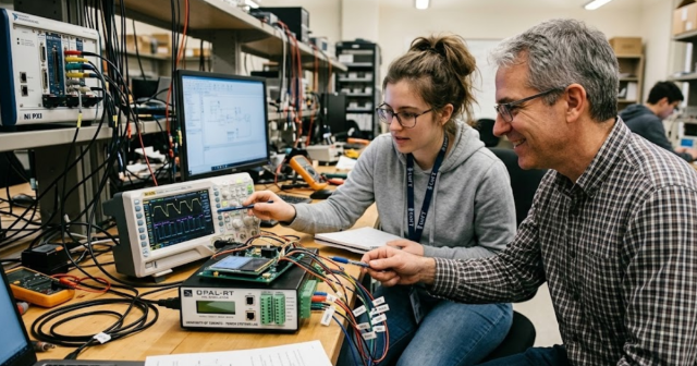
Scaling from academic HIL setups to industrial validation platforms
Practical guidance for moving an academic HIL system from an entry level FPGA real time simulator to a modular platform that supports scalable real time simulation, repeatable tests, and traceable industrial validation results.
Simulation
03 / 20 / 2026
Real-time simulation for validating automotive ECUs in modern vehicle programs
It explains how real-time simulation and hardware-in-the-loop testing improve automotive ECU validation, covering model-to-HIL workflows, use of the Open Alliance Automotive Ethernet ECU test specification, tool selection, and common setup errors.
Simulation
03 / 18 / 2026
Faster firmware testing workflows for embedded systems
Practical guidance on speeding embedded firmware testing with test pyramids, CI automation, tool integration, and hardware-in-the-loop validation while managing fidelity tradeoffs and common traps.
EXata CPS has been specifically designed for real-time performance to allow studies of cyberattacks on power systems through the Communication Network layer of any size and connecting to any number of equipment for HIL and PHIL simulations. This is a discrete event simulation toolkit that considers all the inherent physics-based properties that will affect how the network (either wired or wireless) behaves.