Electrification validation guide for modern engineering teams
Power Systems
01 / 20 / 2026

Key Takeaways
- You’ll ship more reliably when you validate the full closed loop, not isolated parts, and you treat timing and protections as requirements you will measure.
- Pass-fail criteria will save you weeks because they turn tuning debates into clear actions tied to thresholds you can repeat across firmware drops.
- Real-time simulation and HIL testing belong where timing, I/O, and fault sequencing decide outcomes, not only where models look stable.
Electrification validation keeps your control code and power hardware from surprising you on the first full-power run. Electric car sales neared 15 million, or about 18% of total car sales, so more high-voltage systems are shipping on tight schedules. Late failures often start as timing and protection quirks, then turn into rework.
Reliable programs treat timing, power flow, and control as one coupled system. Offline models will help you design, but real-time simulation and HIL testing expose gaps caused by fixed steps, I/O delays, and noisy signals.
What electrification validation requires beyond component-level test plans
Electrification validation works when you prove the full closed loop under the same limits your firmware will face. Controller timing, sensor paths, actuator limits, and protections all get tested as a system. Component checks alone will miss interface faults. A common miss appears after integration. The inverter and motor each pass, then the combined loop trips on a torque step. Current offset, PWM timing, or resolver decoding can push the controller into a corner case. Treat integration tests as first-class. Add delay budgets and mode transitions. Inject expected faults, such as sensor dropout or DC link sag.
“Pass fail criteria stop validation from turning into endless tuning.”
How to define pass fail criteria for electrified systems
Pass/fail criteria prevent validation from turning into endless tuning. Each criterion needs a test condition, an observed signal, and a threshold that triggers action. Include timing and protection outcomes, not only steady-state targets. A torque target alone hides failure modes. Add limits on peak current, recovery time, and protection reaction time. Those details determine whether the system remains safe when the plant behaves badly.
Use criteria you can repeat across every firmware drop:
- Peak current stays under the limit during load steps.
- Protection reacts within the time limit after a short event.
- DC-link ripple stays within the limit at key points.
- Torque error stays inside the band through a cycle.
- Fault recovery reaches a safe state within the time limit.
How to choose real-time simulation versus offline simulation
The main difference between offline simulation and real-time simulation is wall-clock discipline. Offline runs ignore timing so you can sweep parameters and run long cases. Real-time runs enforce fixed steps so you can validate scheduling, I/O delays, and protection sequencing.
Offline is strongest for design questions, such as gain tuning. Real-time is strongest for implementation questions, such as sampling order and deadline margin. Use real time as a check on what the firmware will do.
| Validation question you need answered | Offline simulation fits when | Real-time simulation fits when |
| Stability across the operating map | You need fast sweeps across cases. | You must lock step size and sample order. |
| Timing and comms constraints | You can assume ideal delays. | You must include bus load and latency. |
| Protection reaction time under faults | You want long transients. | You need exact sequencing under timing. |
| Switching ripple affects sensing | You can tolerate slow wall time. | You need deterministic small steps. |
| Integrated loop behaviour with non-ideal I/O | You are shaping architecture. | You are validating loop cadence. |
Where HIL testing fits in an electrification validation workflow

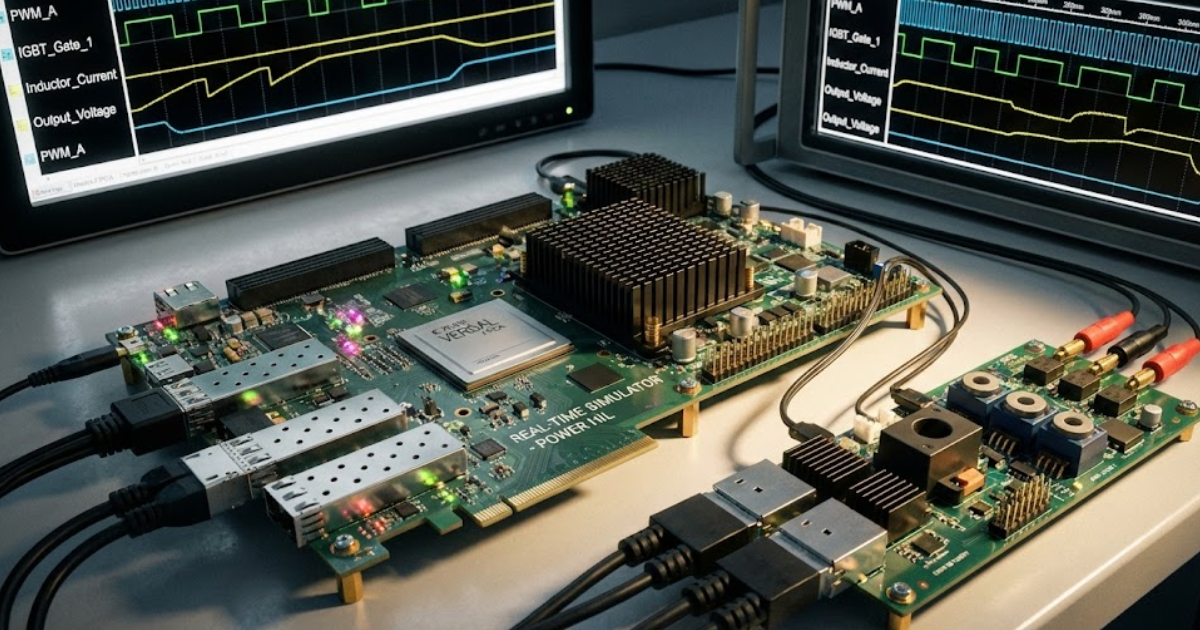
HIL testing fits when your controller hardware must run against a plant that responds in real time. It bridges simulation confidence and the first high-voltage bench run. It also keeps risky fault tests off fragile prototypes. A typical setup runs a motor control ECU against a simulated inverter, machine, and load. You can test calibration, comms timing, and fault handling without spinning hardware. Missed interrupts and scaling errors show up fast with repeatable traces.
Start with a minimal plant that proves loop timing. Automate regression so each firmware drop replays the same cycles and faults. Treat HIL results as release evidence.
How to validate control software under timing and I/O limits
Control software will fail in the lab if timing is treated as “close enough.” The controller runs inside a scheduler with deadlines, shared buses, and interrupt bursts. Validation must prove loops meet rate, sampling stays consistent, and protections execute under load. A familiar pattern is stable plots offline and noise on hardware. Heavy comms traffic pushes the current loop late, and phase delay erodes stability margin. A second pattern is a sensor glitch during a compute spike that delays fallback action.
Measure task time and missed deadlines as pass fail signals. Stress message load and inject jitter. Include realistic ADC quantization and filtering delays.
How to test power electronics behaviour without risking hardware
Power electronics testing stays safer when you prove protection and sequencing before full-power runs. Switching faults can destroy prototypes, so validate trip logic and gate ordering in a controlled loop first. Hardware tests should confirm behaviour, not discover it. A pre-charge routine can trip because the estimator assumes a slower DC-link rise. Deadtime set for one temperature can cause cross-conduction at another. Overvoltage spikes can appear during a load dump when limits react late.
Start with averaged inverter models to validate limits and control structure. Move to switching detail only when it changes the signals you judge. Inject explicit faults and record the reaction sequence.
How to validate electric machine control under fault conditions
Machine control validation must cover faults because unsafe behaviour appears there first. You need evidence that torque limits, current limits, and thermal protection stay stable when phases drop or sensors drift. The goal is controlled degradation with a fast safe-state response. An EV case is an open phase during a high torque launch. An actuator case is a resolver dropout during a position step. The controller must detect, reconfigure references, and keep voltage and current inside limits.
Inject faults that match your topology, not generic flags. Validate detection time and fallback behaviour. Confirm limits stay consistent across modes so calibration stays sane.
“Choose the stack you can keep stable, automate, and audit.”
What multiphase machines change in testing scope and tooling
Multiphase machines expand test scope because fault tolerance creates many valid modes. More phases can smooth torque and reduce per-phase current, yet they add sensors, gating patterns, and reconfiguration logic. Validation must cover mode transitions, fault isolation, and limits per phase group. A 12-phase PMSM adds a twist when phase sets are electromagnetically coupled. A phase loss reshapes current sharing and flux linkages across multiple channels. Reconfiguration must handle that while staying inside thermal limits.
Keep test vectors per mode and per fault. Keep pass fail criteria specific to each mode so evidence stays clear. Treat each mode transition as its own test, not a footnote.
How FPGA real-time simulation supports fast switching fidelity
FPGA real-time simulation matters when protection depends on microsecond-scale timing. FPGA execution can hit smaller time steps with deterministic timing, so gate events and sampling instants stay aligned. That alignment is hard to keep on CPU-only loops at high switching frequency. Desaturation detection and current reconstruction are common pain points. They can look fine offline, then fail when timing is exact. Some teams use OPAL-RT FPGA-based simulation to keep these relationships fixed in closed-loop tests.
Place switching-critical blocks on FPGA and keep slower dynamics elsewhere. Correlate against a safe, limited-power setup, then freeze the model version. This keeps timing evidence repeatable.
Common electrification validation failures that waste time and budget
Teams waste time when model success is treated as system readiness. Tight coupling pushes defects to interfaces, where delays and limits interact. Teams also skip fault injection, then meet faults first on hardware. The scale of field issues shows how hard scrutiny can be. During 2023, 1,000 recalls covering over 39 million vehicles and equipment items were processed. Validation evidence must hold up when questions come.
Protection logic gets treated as separate, then it fights the controller. Timing gets treated as “close enough,” then jitter hunts appear. Put integration, timing, and fault tests earlier, and these patterns lose their bite.
How to choose the right validation stack for your program
Choosing a validation stack is a judgment about the failures you refuse to accept. High safety risk calls for real-time simulation and HIL early. Early concept work calls for more offline sweeps and fewer hardware loops. Start from the highest-risk interaction. Timing risk points to HIL with realistic I/O and scheduler stress. Switching risk points to small time steps on the parts that drive ripple and protection.
Execution discipline will matter more than any single tool choice. OPAL-RT fits when you need deterministic real-time behaviour and repeatable evidence across firmware drops. Choose the stack you can keep stable, automate, and audit.
Real-time solutions across every sector
Explore how OPAL-RT is transforming the world’s most advanced sectors.

Industry applications, Simulation
03 / 31 / 2026
Managing high-frequency switching in real-time EMT simulation
Precision in testing complex power systems is essential to avoid failures, accelerate innovation, and integrate new technologies safely.

Simulation
03 / 30 / 2026
Understanding timestep requirements for modern power converters
Practical criteria for selecting EMT and real time simulation timesteps for power converters, covering switching resolution, control and PWM timing alignment, multirate approaches, and verification checks.

Energy, Industry applications, Simulation
03 / 29 / 2026
Validating data center energy management systems using real-time HIL
This piece explains how AI workload variability affects data centre power stability and how closed-loop HIL testing helps validate EMS control behaviour under site and grid stress.
EXata CPS has been specifically designed for real-time performance to allow studies of cyberattacks on power systems through the Communication Network layer of any size and connecting to any number of equipment for HIL and PHIL simulations. This is a discrete event simulation toolkit that considers all the inherent physics-based properties that will affect how the network (either wired or wireless) behaves.