Why Real-Time Simulation Matters For Advanced Power Electronics Design
Power Electronics
02 / 06 / 2026

Key Takeaways
- Use real-time simulation when converter performance depends on timing, because fixed-step closed-loop testing exposes delays and discretization that offline solvers hide.
- Treat hardware-in-the-loop as a validation workflow, with explicit pass and fail criteria that turn controller updates into repeatable regression tests.
- Pick the simplest plant model that still triggers the same sensing and protection behaviour your controller will see, then protect determinism by managing time step, I/O scaling, and overrun margin.
Real-time simulation will tell you if a converter controller can survive its own timing.
“Advanced power electronics fails in small gaps between a control algorithm and the physical plant it is meant to command.”
Offline simulation can look perfect while hiding delays, quantization, and I/O behaviour that only show up when time is treated as a hard constraint. The price of finding those issues late is steep, since software defects have been estimated to cost the U.S. economy $59.5 billion per year. Real-time simulation shifts that risk forward into a test loop you can control.
The practical stance is simple. If your converter has fast switching, tight protection limits, or multi-rate control, you should treat real-time simulation as a validation step, not a nice-to-have. When the plant model runs with the same clock discipline as the controller, you get answers that align with lab behaviour and production constraints. That makes engineering choices clearer, from sampling rates to fault handling, because the test itself forces timing honesty.
Real-time simulation links control and plant behaviour under load
Real-time simulation closes the loop between your controller and a plant model that must finish every step on schedule. The simulator reads I/O, advances the electrical model, and returns measurements before the next controller deadline. That timing discipline forces control and plant behaviour to interact the way hardware will. Load-dependent nonlinearities also show up in a way that offline runs often smooth over.
For power electronics real-time simulation, the key difference is determinism. A fixed time step means computation, PWM updates, sampling, and protection logic all happen in a repeatable sequence that you can reason about. When current rises, sensors saturate, or duty cycles hit limits, the loop reacts with the same kind of discrete-time behaviour your embedded target will show. That makes it easier to separate a control design issue from a modelling shortcut.
This link matters because converters are timing systems as much as they are power systems. A controller that is stable in an offline variable-step solver can oscillate when the sample-and-hold behaviour is enforced and delays are unavoidable. Treating time as a first-class requirement also clarifies ownership across teams. Control engineers, power stage designers, and test engineers can align on the same clocked experiment instead of debating plots from different assumptions.
Offline models miss timing errors that break advanced converters
Offline simulation tends to hide the exact failure modes that show up when a controller meets hard deadlines. Variable-step solvers, ideal switching, and perfect measurements can mask computation delay, sampling misalignment, and actuator limits. Advanced converters push those limits, so small errors become large in a closed loop. Real-time execution forces every delay to exist somewhere concrete.
Timing errors are not just about speed. They include jitter from scheduling, quantization from ADCs, and phase lag from filtering that looks harmless until protection thresholds get tight. A converter can also fail because a protection routine runs late, not because the threshold is wrong. Offline tests rarely punish you for that kind of lateness, since the solver can take as much time as it needs and still present a smooth waveform.
The operational impact is that offline results often lead you to over-trust margins. You might tune gains to a stability limit that only exists in the offline solver, then watch the loop ring when the controller runs at a fixed rate with real measurement cadence. You also risk missing limit-cycle behaviour tied to PWM resolution, which is invisible when duty cycles are continuous. Real-time simulation is important because it makes those “small” discretization effects unavoidable.
Key benefits for converter development from closed-loop testing
Closed-loop real-time testing helps you validate the control strategy, protection logic, and timing budget as one system instead of three separate tasks. The biggest benefit is earlier confidence in the behaviours that trigger expensive lab rework, like nuisance trips, unstable current regulation, or slow fault response. Those behaviours depend on timing, so you need a timed loop to trust the result.
Converter programs also face scale pressure, and that pressure punishes late discovery. Electric vehicles reached 18% of global new car sales in 2023, which signals high volume expectations for power converters and their control software. When volumes rise, a tuning mistake or protection bug stops being an engineering nuisance and starts becoming a schedule and warranty problem. Real-time simulation turns validation into a repeatable workflow that fits that pace without turning the lab into a bottleneck.
- You will catch control-loop delays that look stable in offline runs.
- You will see protection timing issues before the hardware gets stressed.
- You will validate sensor scaling and sign conventions under clocked execution.
- You will test saturation and limit handling without risking components.
- You will turn controller updates into regression tests that stay consistent.
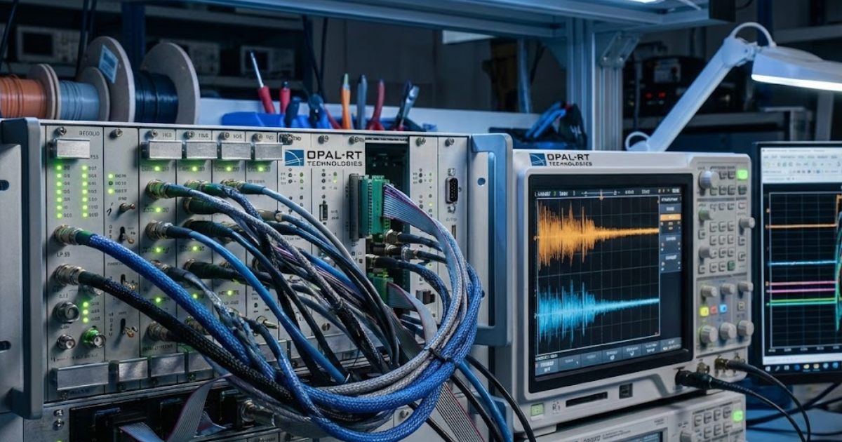
Hardware in the loop workflows for advanced converter design
Hardware-in-the-loop testing connects your physical controller to a real-time plant model so you can validate behaviour under clocked, closed-loop conditions. Signals move through actual I/O, so latency, scaling, and numeric limits are part of the test. This workflow is the shortest path to proving that code, protections, and sampling choices work on hardware. It also helps you separate a controller defect from a power stage issue earlier.
A typical workflow starts with a plant model that can run at a fixed step, then maps the controller’s analog and digital signals into the simulator, and finally builds an automated set of tests for steady-state, transients, and faults. One concrete example is a team validating an advanced converter design for a high-voltage inverter controller at a 20 kHz control rate while injecting a DC-link voltage sensor offset and a staged overcurrent event. The controller’s trip timing, recovery behaviour, and current regulation can be checked against explicit pass and fail limits without touching a high-power bench. Engineers often run this style of test on an OPAL-RT simulator when they need deterministic timing and repeatable fault insertion.
The discipline to adopt here is to treat HIL results like software test results, not like a demo. A failing test should point to a specific timing path, scaling mismatch, or state-machine transition you can fix and re-run within hours. That keeps the lab focused on validating power hardware, not debugging basic logic errors. It also makes cross-team reviews simpler, since the same test can be replayed after every controller revision.
“The best teams treat timing as a requirement and tests as artifacts.”
Choosing model fidelity and time step for stable execution

Model fidelity in real time is a tradeoff between electrical detail and computational deadlines. A smaller time step captures faster switching behaviour but consumes more compute per second of simulation. A simpler model runs faster but can hide ripple, harmonics, or protection triggers tied to waveform shape. Stable execution comes from choosing the lowest fidelity that still answers your specific control and protection questions.
Start from the controller’s sampling period, then work backward to the plant step that keeps phase lag and discretization within your tolerance. If the control loop reacts to ripple, you need a model that preserves the ripple shape at the step you can afford. If the control loop reacts mainly to averages, an averaged plant model can be more useful because it buys timing headroom for I/O and monitoring. The right choice is the one that keeps timing deterministic while still producing the measurement features your code actually reads.
| Checkpoint you should verify | What a solid choice looks like | What problem it avoids |
|---|---|---|
| Your plant step matches the fastest control deadline you enforce. | The simulator finishes each step with consistent margin, not occasional overruns. | Late samples that show up as random instability or nuisance trips. |
| The switching detail matches what the controller measures and filters. | The model keeps the waveform features that pass through your sensing chain. | False confidence from a smooth signal that never stresses protections. |
| I/O scaling is checked with known stimulus and expected units. | Every measured value is validated in volts, amps, and per-unit where used. | Wrong gains and sign errors that look like control tuning problems. |
| Protection logic is tested against timing, not just threshold values. | Trip decisions occur within the required number of control periods. | Protection that “works” in plots but reacts too late on hardware. |
| Numeric limits are exercised where saturation is expected. | Integrator windup and limiter behavior is validated under stress conditions. | Recovery failures that only appear after long runs or repeated events. |
Common mistakes when using real-time simulators and fixes
Most real-time simulation failures come from treating the simulator like an offline tool that happens to run faster. Overloaded models miss deadlines, poorly scaled I/O ruins controller interpretation, and untested numeric limits create surprises during fault events. Fixing these issues is less about buying more compute and more about test discipline. The best teams treat timing as a requirement and tests as artifacts.
Start by policing step overruns with the same seriousness as a failing protection test, since one overrun can invalidate a long run of “good” data. Next, lock down signal contracts, meaning units, polarity, update rate, and filtering, then review them every time the controller changes. After that, stress numeric limits on purpose, since saturation and windup are common in converter control, and they often hide behind clean waveforms. Finally, keep your pass and fail criteria explicit, so every test run ends with a clear call, not a debate.
The judgment to carry forward is that advanced converters reward teams that respect timing details early and often. Offline simulation is still valuable for design exploration, but it should not be the final word on closed-loop behaviour. Teams that use OPAL-RT as part of a disciplined real-time workflow tend to get better outcomes because the test forces every assumption to be measurable. That’s what turns simulation from a picture into a decision you can stand behind.
Real-time solutions across every sector
Explore how OPAL-RT is transforming the world’s most advanced sectors.

Industry applications, Simulation
03 / 31 / 2026
Managing high-frequency switching in real-time EMT simulation
Precision in testing complex power systems is essential to avoid failures, accelerate innovation, and integrate new technologies safely.

Simulation
03 / 30 / 2026
Understanding timestep requirements for modern power converters
Practical criteria for selecting EMT and real time simulation timesteps for power converters, covering switching resolution, control and PWM timing alignment, multirate approaches, and verification checks.

Energy, Industry applications, Simulation
03 / 29 / 2026
Validating data center energy management systems using real-time HIL
This piece explains how AI workload variability affects data centre power stability and how closed-loop HIL testing helps validate EMS control behaviour under site and grid stress.
EXata CPS has been specifically designed for real-time performance to allow studies of cyberattacks on power systems through the Communication Network layer of any size and connecting to any number of equipment for HIL and PHIL simulations. This is a discrete event simulation toolkit that considers all the inherent physics-based properties that will affect how the network (either wired or wireless) behaves.