How to build a protection relay testing workflow utility engineers trust
Power Systems
09 / 16 / 2026
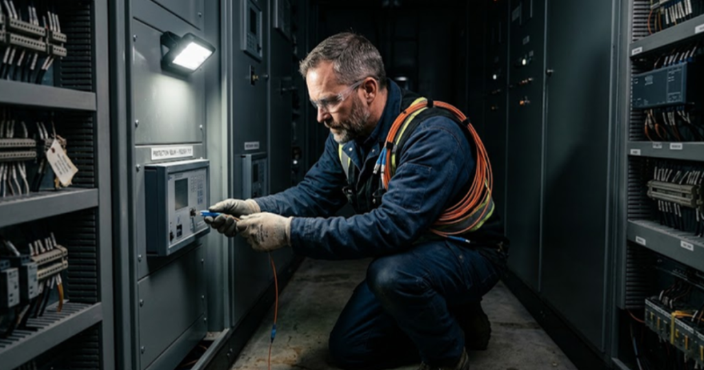
Key Takeaways
- Element verification and scheme validation are separate jobs, and most testing programs only finish the first one.
- Closed loop simulation is what exposes coordination, reclosing and inverter interaction behaviour that a fixed injection waveform cannot reproduce.
- A reusable fault case library tied to the settings file turns setting errors into a regression check instead of a field discovery.
A protection relay testing workflow earns its keep when it catches a setting or logic error before the scheme goes live rather than after a fault exposes it.
That bar has moved. Almost 70 GW of new solar capacity is scheduled to come online across 2026 and 2027, a 49% increase in United States operating solar capacity against the end of 2025. Fault current from those plants is limited and shaped by controls, so distance and directional elements see behaviour the electromechanical era test plan never contemplated. Secondary injection alone confirms the relay does what its settings say while missing that the settings suit the wrong network.
The fix isn’t more injection points. It’s closing the loop, putting the relay in front of a simulated system that reacts to its trip decisions, then replaying the fault cases your planning studies call credible. You’ll still run element checks. What shifts is that the scheme gets validated as a system before anyone energizes it.
What protection relay testing actually proves about a scheme
Protective relay testing proves three separate things. The first is that relay hardware measures correctly. The second is that settings match the approved coordination study. The third is that the scheme clears a fault inside the time the system tolerates. Most programs prove the first two well and the third almost never.
A distance element bench check confirms that the reach point trips at 85% of line impedance. It says nothing about what happens when the remote terminal teleprotection signal arrives 12 ms late after a communications failover and the local relay falls back to zone 2 timing. That second question is answerable only when the relay runs against a model of the network it sits in.
Coordination studies produce the settings. Testing is where you learn if those assumptions survived contact with the actual topology, instrument transformer ratios and communications latency. Treating the two activities as unrelated is how correct settings end up protecting the wrong system.
“Most programs prove the first two well and the third almost never.”
Where steady state injection testing stops being sufficient
Secondary injection stops being sufficient the moment a relay decision affects what that relay measures next. Injection replays a fixed waveform and scores the response against expected pickup and timing. It cannot show breaker reclosing into a weakened source, generator angle swing after the first trip, or an inverter control loop reacting to the sag the relay just extended.
Picture a 138 kV line with automatic reclosing on a bus that also carries a 60 MW solar plant. Open loop injection confirms that the relay trips and initiates a reclose on schedule. Only a closed loop run shows the plant riding through the first sag, tripping on the second, and leaving the reclose to energize a source that’s far weaker than the setting file assumed.
Relays behave exactly as configured while the scheme produces an outcome nobody intended, because every device was verified in isolation. Injection stays fast and useful for element verification. It just can’t answer questions about interaction, which is where modern schemes fail.
How closed loop relay testing works with real time simulation
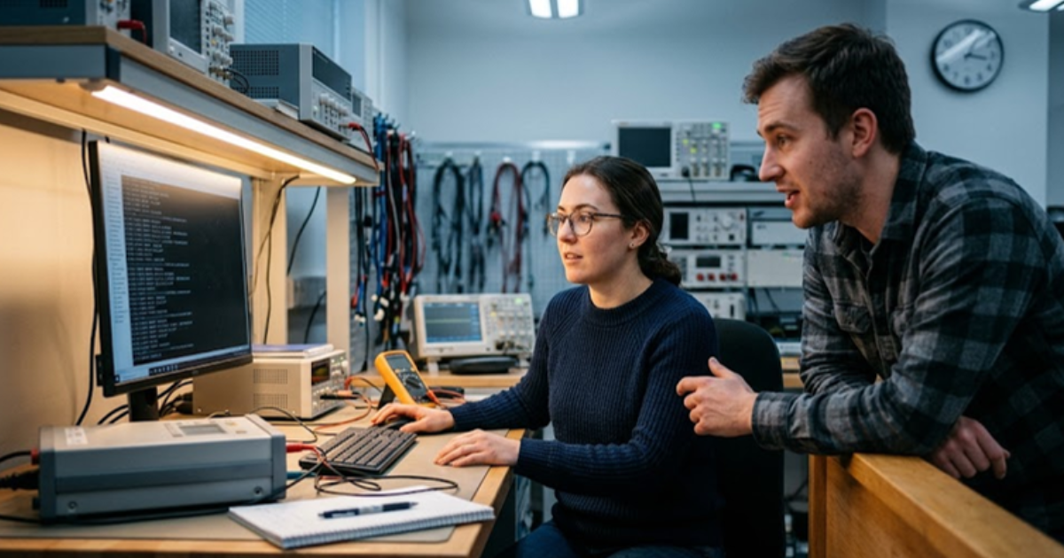
Closed loop relay testing puts a physical relay inside the control path of a power system model running in real time. The simulator computes network response every 25 to 50 microseconds, streams voltages and currents to the relay, accepts the trip and close contacts back, and applies them to the model breaker in the same time step.
Interfacing happens two ways. Amplified analogue signals drive the inputs on a traditional relay, while digital substation schemes take IEC 61850 sampled values into the process bus port. Trip and block signals return as GOOSE messages, and synchrophasor streams follow IEEE C37.118 when wide area elements are in scope. Platforms such as HYPERSIM from OPAL-RT publish all three from one model, so digital and conventional relays share a bench.
Latency budgeting matters more here than raw model size. A GOOSE trip arriving 4 ms late inside the loop produces a different clearing time than the field will see, so publisher and subscriber timing get measured during setup rather than assumed.
Choosing between open loop injection and closed loop validation
The main difference between open loop injection and closed loop validation is feedback. Injection plays a recorded or computed waveform at the relay and grades the response. Closed loop lets the relay act on the system it’s measuring, surfacing coordination, stability and recovery behaviour a fixed playback file cannot contain.
Cost and schedule pull in opposite directions. A test set and a settings file get you element verification in an afternoon. A real time model of the substation takes days to build the first time, then costs almost nothing to rerun for every setting revision after that.
| Question the test has to answer | Open loop injection | Closed loop simulation |
| Does the element pick up at the configured reach | Answered quickly with a standard test set | Answered too, though the setup effort is hard to justify alone |
| Does the scheme clear before a nearby machine loses synchronism | No machine model is present, so it cannot answer | Answered directly, since generator dynamics run inside the loop |
| How does reclosing behave into a weakened inverter fed source | Limited to a waveform somebody recorded earlier | Reproduces the second shot, since the model reacts to the first trip |
| Does GOOSE timing hold up under station traffic | Bench timing only, with no other messages present | Measured with the full process bus message set running |
| What happens when a setting gets revised during commissioning | Needs a fresh injection plan and a site visit | Rerun of the existing case library, done in minutes |
Building fault scenario libraries that cover credible grid conditions
A fault scenario library is the reusable set of cases a scheme gets tested against every time its settings move. Build it from planning studies you already trust, covering peak and minimum load topology, N-1 outages that shift source impedance, and the fault types and locations your coordination study used.
Five case families cover most of what a transmission scheme meets in service.
- Bolted three phase and single line to ground faults at 0%, 50% and 100% of line length
- High resistance ground faults near the edge of the ground element reach
- Faults that develop from one phase to two during the clearing sequence
- Reclose onto a persistent fault with the remote terminal already open
- Loss of the teleprotection channel during an in zone fault
Coverage is worth more than volume. Human performance causes such as incorrect settings, logic errors and as left personnel error account for 39% of all misoperations recorded across 2020 to 2024, which is exactly the category a test library closes. A library that reruns on every settings revision turns those causes into a regression problem.
Failure modes that let misoperations reach the field
Most misoperations that survive testing come from gaps in the test plan rather than defects in the relay. The usual gaps are untested logic branches, settings revised after the last validation run, instrument transformer saturation nobody modelled, and communications behaviour verified on a quiet bench instead of a loaded network.
Breaker failure logic is the recurring offender. It’s the branch nobody exercises, because triggering it needs a stuck breaker, so the initiate path gets checked while the interaction with adjacent zone 2 elements goes unverified. Closed loop testing makes that case cheap, since the model breaker simply refuses to open.
Version drift runs a close second. Settings get adjusted during commissioning, the relay file moves ahead of the tested baseline, and the validation record quietly stops describing the device in service. Tying the case library to the settings file inside one change control system removes the ambiguity, because a revision that hasn’t been rerun shows up as an open item.
“Most misoperations that survive testing come from gaps in the test plan rather than defects in the relay.”
What disciplined relay testing gives utility engineers over time
Disciplined relay testing compounds. Every scheme you validate in closed loop leaves behind a reusable model, a case library and timing measurements the next project starts from, so the effort curve bends down while coverage goes up. That’s the return, and it shows up in outage statistics before it shows up in test reports.
Crews feel it first. A commissioning team with a recorded closed loop run for every zone and logic branch spends its site time proving the installation instead of debugging the design. Engineering managers feel it later, when a settings revision costs an afternoon of reruns instead of a night crew and a line outage.
Neither outcome depends on a larger simulator. Both depend on treating the relay as one component inside a system model, and refusing to sign off on a scheme that hasn’t been exercised against the conditions it will meet. Teams building benches with OPAL-RT reach the same judgment, that the model is the durable asset. Keep it current, keep the case library tied to the settings file, and the scheme stops surprising you.

Power Electronics
09 / 12 / 2026
Capturing GaN switching transients in real time converter models
A technical look at how timestep selection, solver architecture and model partitioning decide how much of a GaN switching transient a real time converter model actually reports.

Power Electronics
09 / 10 / 2026
How to model switching losses when simulating high frequency converters on FPGA
A technical look at how switching loss accounting inside an FPGA solver shapes the efficiency estimates engineers report for high frequency power converters.

Energy
09 / 09 / 2026
Renewable energy simulation for grid integration studies
A practical look at how renewable energy simulation supports grid integration studies, covering the split between electromagnetic transient and phasor-domain methods, the modelling errors that invalidate results, and how the two domains combine on one project.