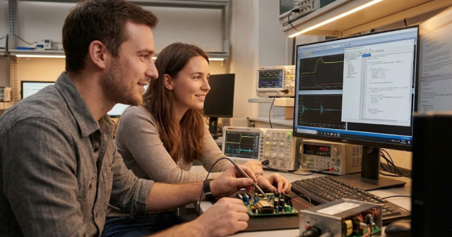
7 real power hardware‑in‑the‑loop examples that sharpen your simulation strategy
08 / 22 / 2025

Sharper test results start with closing the loop between your simulator and actual power hardware. Once your controller sees the same voltages, currents, and timing it will face on the bench, design choices get clearer. Corner cases surface early, tuning gets more precise, and confidence rises for the next build. You also gain a safe path to stress fault scenarios that would be risky or expensive to stage on a full rig.
You work under tight schedules, finite budgets, and the need for traceable proof. Power electronics behave at microsecond scales, so a deterministic loop is the only way to vet timing, protection, and stability. Modern setups combine a real-time digital simulator, a high bandwidth power interface, and accurate sensing for clean feedback. That mix turns models into a responsive test bench, keeping progress moving while protecting equipment.
Why you need power hardware‑in‑the‑loop for sharper simulation results
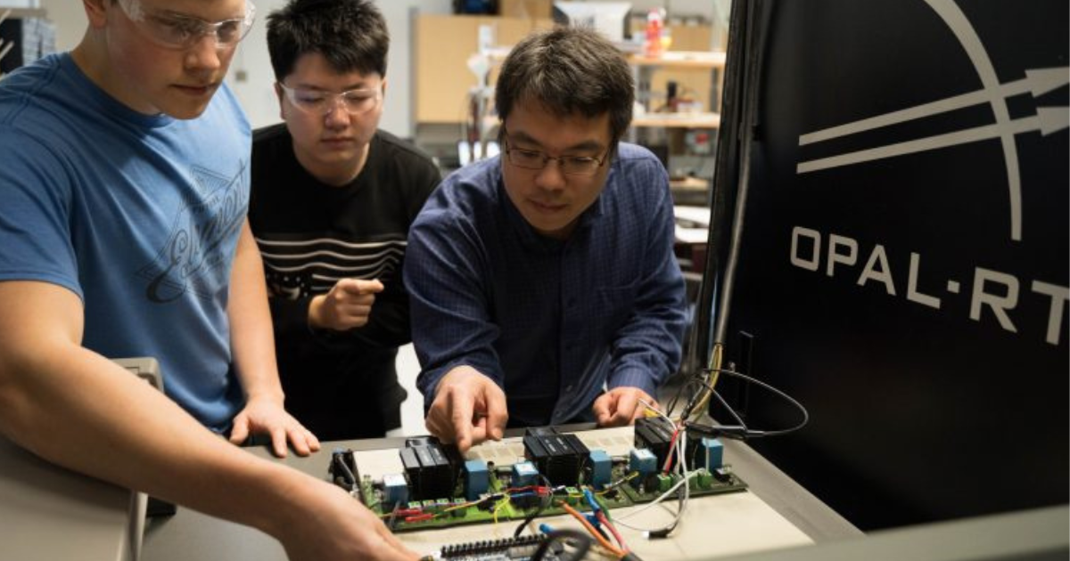
Hardware-in-the-loop (HIL) closes the control loop between your controller under test and a plant model running on a real-time simulator. Power hardware-in-the-loop (PHIL) extends that concept by inserting a power interface so the controller drives, and receives feedback from, actual power signals. This interface combines a bidirectional amplifier, precision measurement, and protection so your equipment exchanges current and voltage with the simulated plant. That structure preserves the physics your control software cares about, including non-linearities, switching ripple, and sensor dynamics. With power hardware in the loop, those signals look and feel like the final lab setup, which shortens debug time and sharpens evaluation results.
Lab teams value this because high-fidelity feedback reveals timing margins that software-only runs tend to hide. Fault insertion becomes repeatable, measurement uncertainty stays visible, and model assumptions can be challenged without risking damage to a high-power rack. Tuning across component tolerances, cable inductance, and filter placement becomes practical when the controller experiences the same current slew, delay, and quantisation effects it sees on hardware. The result is a more trustworthy control loop, backed by plots and records that stand up to design reviews.
7 real power hardware‑in‑the‑loop examples that sharpen your simulation strategy
Teams often ask where PHIL pays off first. Projects that mix fast-switching devices, tight control loops, and grid rules tend to benefit. Closed-loop testing reveals timing issues, filter choices, and controller edge cases that pure modelling can miss. The right setup pairs your digital simulator with a high fidelity power interface, precise measurement, and safe fault insertion.
1. Testing power converter control algorithms under fault conditions
Short circuits, line sags, blown fuses, and step loads should not be your first encounter during full-power commissioning. Power hardware-in-the-loop lets you inject those events, record the response, and verify that current limiting, desaturation handling, and shutdown logic behave as designed. Because the simulator owns the plant, you can dial fault magnitude, duration, and phase angle with repeatable precision. That precision makes it easier to confirm PWM behaviour, anti-windup handling, and latch states across hard faults and soft recoveries.
A typical setup models the source and passive network on the real-time simulator, feeds a power amplifier, then returns measured current and voltage to the controller. You can verify blanking times, gate-drive interlocks, and comparator thresholds while the loop stays closed. The method surfaces cross-coupling between sampling, delay lines, and digital filters that small-signal analysis often glosses over. With power hardware in the loop, you build evidence on how protection trips, how it clears, and what the controller remembers after a restart.
2. Simulating grid‑connected inverter behaviour in renewable energy systems
Grid-tied inverters must hold up across voltage dips, frequency swings, and flicker limits, all while meeting reactive power and ride-through rules. A PHIL setup can subject a converter to those conditions with a controllable grid model and a safe path to inject imbalances or harmonics. Engineers can evaluate phase-locked loop design, current controller bandwidth, and droop curves without moving to a full test yard. The result is a measured response that shows overshoot, settling time, and current quality under clear operating points.
Hardware in the loop power electronics help you validate grid support functions, such as voltage control, frequency support, and low-voltage ride through. You can sweep fault depth and clearing time, then compare the inverter’s control traces against compliance thresholds. The same setup supports islanding studies, grid-forming modes, and transitions back to grid-following under controlled conditions. Data from these runs informs filter sizing, current limits, and firmware settings before field trials.
3. Accelerating control development for electric vehicle powertrains
Powertrain teams juggle traction inverters, on-board chargers, and DC to DC converters while balancing range, thermal safety, and drive feel. Power hardware-in-the-loop lets you connect a physical inverter to a simulated machine model and road profile so control loops see believable torque dynamics. You can examine current ripple at high switching ratios, sensor quantisation, and torque tracking under aggressive transients. Because models execute deterministically, your tuning aligns with the latencies and delays your controller will face in the lab.
Hardware in the loop power electronics also shortens time-to-first-drive for new control ideas. You can couple a battery emulator, resolver or encoder emulation, and a plant model to explore torque limits and field weakening logic. Network traffic through controller area network (CAN) or Ethernet can be included so calibration scripts face the same bus load they will meet later. The loop keeps current under control while revealing thermal margins, foldback logic, and limp modes under stress.
4. Verifying microgrid controller performance
Microgrid controllers must coordinate grid-forming sources, storage, and protection while riding through faults and switching events. Power hardware-in-the-loop allows islanding, black start trials, and resynchronisation to main supply without exposing a site. Engineers can validate droop settings, phase jump limits, and power sharing across units under clean, repeatable scenarios. Plots show how the controller manages transients, maintains voltage quality, and restores load without excessive curtailment.
A PHIL bench can switch the microgrid from grid-following to grid-forming, apply load steps, and force breaker events while recording sequence of events. That makes it easier to tune phase-locked loops, synchronisers, and protection coordination before site work. With power hardware in the loop, engineers can also verify control logic for storage charge and discharge limits across temperature and age models. The reduction in on-site surprises is measurable, and the audit trail supports approval.
5. Protection system and distributed generation controller testing
Protective relays and distributed generation controllers should be checked for speed, security, and sensitivity before field wiring is touched. A PHIL setup can inject fault currents, phase imbalance, or frequency deviations into hardware so trip curves and anti-islanding logic are verified. You can repeat each case under noise, harmonic pollution, and sensor error to quantify margins. Captured traces confirm pickup thresholds, timing, and breaker commands with time alignment to microseconds.
This approach also helps check interaction between inverter current limits and protection settings, which often explains nuisance trips. The simulator can vary fault impedance and source strength so test coverage includes weak-grid cases that are hard to stage on a bench. With power hardware in the loop, teams document interlocks, ride-through behaviour, and fail-safe paths across many lineups. That evidence feeds commissioning plans, site procedures, and performance guarantees with fewer unknowns.
6. Integrating digital twins for predictive maintenance
A digital twin links a physics-based model with telemetry from a matching asset so you can forecast behaviour and schedule service. Power hardware-in-the-loop lets you prove the twin’s usefulness by driving hardware with faults and ageing conditions pulled from recorded data. Thresholds for alarms and fault signatures can be tuned while the controller reacts to realistic waveforms. Teams see which signals carry the most value, which sensors need better placement, and which diagnostics reduce false alarms.
Once confidence grows, the same bench can train analytics that support artificial intelligence (AI) based detection across a fleet. The simulator streams labelled events while the power interface and sensors keep the controller honest. Hardware in the loop power electronics provide timing and noise that help models avoid brittle behaviour when deployed. The outcome is a maintenance plan grounded in measured responses, not just offline studies.
7. Supporting cybersecurity testing under simulated threats
Control networks and power electronics interact tightly, so malformed traffic or spoofed setpoints can stress both software and hardware. A PHIL setup lets you replay network faults, time sync errors, and configuration mistakes while the controller drives a live power interface. You can observe how failsafe states respond, which alarms appear, and how quickly the plant returns to service after containment. Evidence from these runs supports reviews of secure boot, update processes, and access control settings.
Power hardware in the loop also helps quantify the electrical impact of cyber events that change setpoints or modes. Engineers can correlate packet captures with current surges, voltage dips, or oscillations to demonstrate risk to stakeholders. The closed loop allows safe testing of rate limits, watchdogs, and safe-state logic without exposing a facility. That data turns abstract findings into concrete improvements for system hardening.
Closed-loop testing with power hardware-in-the-loop offers measured performance, not assumptions. Engineers gain a platform that stresses firmware safely, records fast events, and confirms margins before full-power trials. The approach scales from low-voltage prototypes to higher ratings as amplifiers and models grow with project scope. Confidence rises because results arrive as repeatable traces, clean pass or fail criteria, and clear evidence tied to test cases.
Modern setups combine a real-time digital simulator, a high bandwidth power interface, and accurate sensing for clean feedback.
How hardware in the loop power electronics help you validate faster
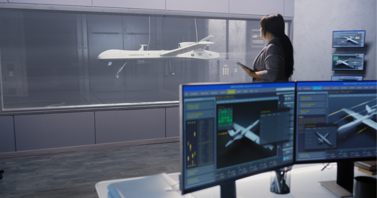
Short design cycles reward teams that remove latency from feedback loops, reviews, and test iteration. Hardware in the loop power electronics reduce waits by giving your controller a realistic plant at your desk, with safe, scripted test cases. Engineers can push a new build, run the same set of transients, and compare key metrics minutes later. Because the simulator stays deterministic, changes in plots reflect your code or parameters, not an unpredictable bench setup.
That rhythm shortens model and firmware alignment, trims the number of full-power attempts, and compresses handoffs across groups. Teams stop blocking each other since the bench supports parallel shifts from model-in-the-loop (MIL), to software-in-the-loop (SIL), to HIL and PHIL on shared infrastructure. Data becomes a shared reference with labelled events, exact timestamps, and scripts that keep experiments consistent. The net effect is faster validation without sacrificing rigour, which is exactly what fast-moving programs require.
How power hardware in the loop reduces your test‑cycle cost and risk
Power tests consume energy, parts, floor space, and time, so each pass should carry high learning value.
Power hardware in the loop removes many early build risks by moving fault and stress trials to a controllable bench. Damage risk drops because amplifiers, breakers, and software protections limit exposure while still providing authentic signals. You spend fewer components on trial-and-error, and you reserve the high-power rig for confirmation, not exploration.
Coverage also improves because scripted scenarios sweep across tolerances, component ageing, and conditions that are tough to stage with physical loads. Engineers get cost clarity from shorter setup time, reusable test scripts, and fewer reworks caused by late surprises. Procurement sees cleaner plans for equipment and spares since the team validates protection and performance earlier. Risk falls because evidence arrives sooner, and decisions rest on measured behaviour rather than optimistic assumptions.
How OPAL‑RT solutions bring real‑time power hardware‑in‑the‑loop into your lab
OPAL-RT provides real-time digital simulators that combine central processing unit (CPU) and field-programmable gate array (FPGA) computing to run high-fidelity models with microsecond steps. RT-LAB software ties execution, model management, and acquisition in one workflow while staying open to MATLAB/Simulink, Functional Mock-up Interface (FMI)/Functional Mock-up Unit (FMU), and Python workflows. The eHS and ARTEMiS toolboxes support switching power electronics and network studies, and HYPERSIM scales to large systems when projects grow. Power interfaces, measurement options, and safety features connect controllers to the simulator so power hardware-in-the-loop stays stable, repeatable, and safe. Teams gain deterministic performance across fast events, clear visibility into timing, and the capacity to test more ideas each week.
What stands out is fit for purpose with common lab constraints, not a locked stack. You can start with a single chassis, add I/O as needs grow, and connect to your existing amplifiers or measurement gear. OPAL-RT supports integration with artificial intelligence (AI) and cloud toolchains when you want to blend digital twins with PHIL campaigns. Global teams rely on the same platforms, which eases knowledge sharing, reproducible scripts, and consistent training across sites. Choose OPAL-RT for proven real-time simulation, trusted support, and evidence you can present with confidence.
Common Questions
What is power hardware-in-the-loop and how does it improve my test reliability?
Power hardware-in-the-loop (PHIL) is a method where your real controller connects to a simulated power system through a power interface, exchanging actual current and voltage signals. This setup replicates real conditions more accurately than software-only simulations, especially in fast-switching and fault-sensitive applications. PHIL helps detect control errors, delay mismatches, or protection flaws earlier in the validation cycle. OPAL-RT solutions provide real-time performance and open integration to help you build trust in your results without sacrificing lab safety.
Can I use power hardware-in-the-loop for electric vehicle component testing?
Yes, PHIL is highly effective for electric vehicle (EV) powertrain development, including inverters, chargers, and DC converters. It lets you simulate drivetrain dynamics and road conditions while your controller manages real power flow. This helps evaluate torque response, current ripple, and thermal limits before full bench commissioning. OPAL-RT supports these workflows with flexible interfaces and models that grow with your system architecture.
How does PHIL help reduce testing costs and development delays?
Using PHIL early reduces risk by allowing safe and controlled fault testing, repeatable transients, and realistic signal exchange without full-power setups. It minimizes hardware damage, compresses debug time, and ensures fewer surprises during physical commissioning. Engineers get faster validation, while decision-makers see lower rework rates and more predictable delivery timelines. OPAL-RT tools bring these efficiencies into labs of all sizes with scalable, cost-effective platforms.
Is power hardware-in-the-loop useful for microgrid simulation and testing?
PHIL is ideal for validating microgrid controllers under scenarios like islanding, black start, or re-synchronisation without relying on field infrastructure. You can test droop control, breaker sequencing, and distributed generation coordination under realistic voltage and current feedback. OPAL-RT simulators help teams model complex grid behaviour and connect it with actual hardware for precision testing. That makes it easier to fine-tune controller logic and meet project or regulatory requirements.
What do I need to set up a PHIL bench in my lab?
To build a PHIL test setup, you need a real-time digital simulator, power amplifier or interface, accurate sensing, and a controller under test. Each part must support microsecond-level timing to maintain stability and match your model fidelity. OPAL-RT platforms combine high-speed simulation, open architecture, and safety-integrated power interfaces to help you deploy PHIL setups that scale with your validation needs.
EXata CPS has been specifically designed for real-time performance to allow studies of cyberattacks on power systems through the Communication Network layer of any size and connecting to any number of equipment for HIL and PHIL simulations. This is a discrete event simulation toolkit that considers all the inherent physics-based properties that will affect how the network (either wired or wireless) behaves.
