A complete guide to hardware-in-the-loop pre‑commissioning and validation
Industry applications
10 / 22 / 2025
Pre‑commissioning with hardware‑in‑the‑loop lets you find problems when fixes are cheap. Engineers see wiring mistakes, timing faults, and control logic gaps before a controller leaves the bench. That saves hours on site, protects schedules, and supports safer operation. It also gives teams clear data to defend choices with managers, auditors, and certification bodies.
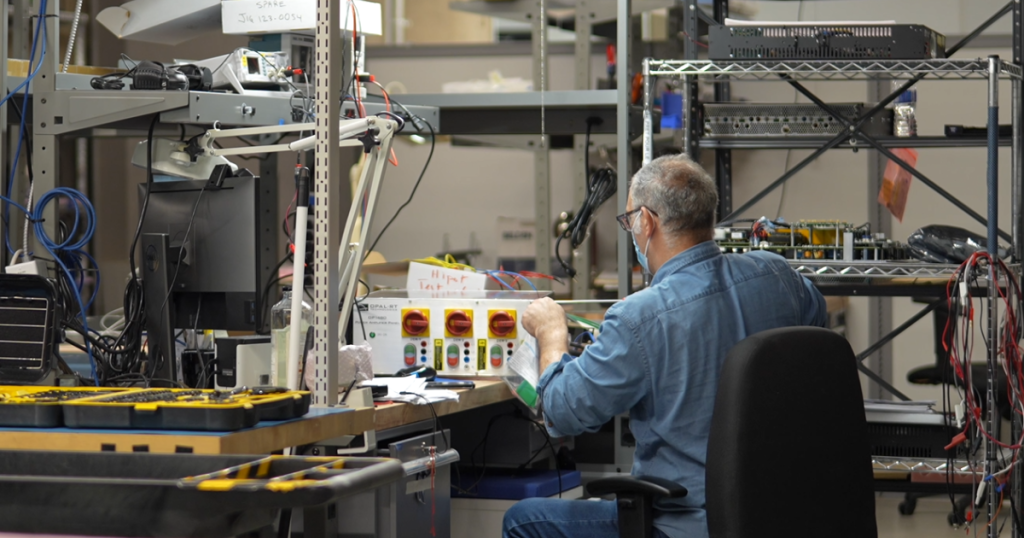
Hardware‑in‑the‑loop blends high‑fidelity simulation and physical controllers to validate behaviour in closed loop. You connect your control hardware to a real‑time simulator that emulates the plant with millisecond or microsecond precision. That pairing helps you stress edge cases without risking assets, people, or lab facilities. It also creates a repeatable test context that software, safety, and compliance teams can trust.
Why pre-commissioning matters for complex engineering systems

Large control projects rarely fail due to a single cause, and most setbacks trace back to issues that surface late. Pre‑commissioning shifts tests left into the lab so you find integration faults while changes are still simple. Teams reduce time on site, lower travel costs, and cut overtime that arises when late bugs collide with deadlines. Stakeholders gain clearer status because results are measured against known baselines, not ad hoc field checks.
Pre‑commissioning also protects hardware and people by proving core behaviour before energization. You can try start‑up sequences, fault ride‑through, and recovery routines without risking equipment. Engineers gain confidence in parameter ranges, limits, and protections through structured runs. That preparation supports a smoother handover to site crews and service partners.
Difference between pre-commissioning and commissioning with HIL
The main difference between pre commissioning and commissioning with HIL is location and risk: pre‑commissioning uses a lab‑based, hardware‑in‑the‑loop test bed to validate functions before any field work begins, while commissioning happens on site with the actual plant under operational constraints. Pre‑commissioning focuses on models, interfaces, and controller logic using simulated plant dynamics. Commissioning confirms installation quality, safety systems, and performance with live equipment. Both phases complement each other, but HIL front‑loads learning, reduces on‑site surprises, and shortens punch lists.
Pre‑commissioning also standardizes repeatable tests and data capture, which pairs well with agile software updates. Commissioning adds constraints such as access windows, site rules, and coordination with other trades. A balanced approach treats HIL as the primary risk reducer, then uses field checks to confirm mechanical, electrical, and process details.
| Aspect | Pre‑commissioning with HIL | Commissioning on site |
| Test scope | Control logic, protection, diagnostics, fault cases | Wiring, installation, safety interlocks, performance |
| Risk profile | Low physical risk, high iteration speed | Higher physical risk, limited iteration time |
| Schedule impact | Pulls learning forward, shortens site work | Final verification, subject to site constraints |
| Data quality | Repeatable scenarios, high‑resolution logs | Mixed data quality, constrained runtime |
| Cost profile | Lower cost per iteration, lab resources | Higher cost per issue, site resources |
What hardware-in-the-loop testing means for engineers

Hardware‑in‑the‑loop (HIL) testing connects a real controller to a real‑time simulator that emulates the plant it will control. The simulator runs physics models fast enough to exchange signals with the controller through analogue, digital, or communications interfaces. That closed loop allows realistic timing, noise, and fault conditions without exposing equipment to hazards. Engineers use this setup to validate algorithms, tune parameters, and de‑risk start‑up.
HIL hardware in the loop and HIL technology is valuable across energy, automotive, aerospace, and academia projects where safety, accuracy, and timing matter. You can keep the same rig across sprints, which means results are comparable and audits are simpler. Toolchains also carry forward from modelling to execution, which reduces manual rework.
Pre-commissioning with hardware-in-the-loop lets you find problems when fixes are cheap.
How hardware-in-the-loop works step by step
A clear understanding of signal flow and timing helps you set expectations for HIL runs. Each element in the loop has latency, scaling, and limits that shape results. Good practice starts with simple plant models and grows detail as the controller settles. Safety layers let you explore faults without risking hardware.
Model the plant and set real‑time targets
Start with a plant model that captures the dynamics your controller relies on, such as electrical, mechanical, or thermodynamic behaviour. Choose fixed‑step solvers and discretization that meet real‑time deadlines on your simulator. Validate the model offline, then profile it on target hardware to confirm step‑time margins. Keep fidelity honest by comparing against measurements or accepted references.
Move to real‑time execution once profiling shows stable headroom for your target step size. Align interface variables, units, and scaling with what the controller expects. Define test scenarios for start‑up, steady state, and fault cases that reflect credible operating states. Maintain version control for models, parameters, and scripts so any result can be reproduced.
Integrate the controller and map signals
Connect your control hardware through I O modules that match voltage, current, and timing requirements. Map analogue, digital, and serial fields to model variables with clear naming and units. Confirm pinouts, pull‑ups, and grounds to avoid masking logic issues with wiring mistakes. Include timestamped logging on both sides to make timing comparisons easy.
Exercise basic I O first, then add setpoints, feedbacks, and interlocks. Watch for sample‑rate mismatches, quantization effects, and filter delays that can hide stability problems. Introduce communications frames, timeouts, and error codes if your system uses fieldbuses. Keep notes on any shim or adapter layers so future reviewers understand the test setup.
Close the loop with I/O conditioning and safety
Condition signals using appropriate isolation, attenuation, and filtering so the controller receives clean inputs. Implement emergency stops, watchdogs, and current limits that trip before hardware damage is possible. Add software guards in the model to prevent non‑physical states that can mislead tuning. Verify safety paths early to avoid confusion during fault injection.
Test negative and out‑of‑range values to prove that limit checks behave as intended. Emulate sensor failures, stuck actuators, and communication faults with controlled patterns. Observe how the controller recovers and confirm that logs capture key moments. Document safe reset steps so junior staff can repeat tests with confidence.
Run test scenarios and collect high fidelity data
Execute start‑up, step changes, and stress tests to exercise the control law across its operating envelope. Sweep gains, time constants, and thresholds to map sensitivity and stability. Inject supply dips, load spikes, and oscillations to confirm protection logic and diagnostics. Track pass and fail outcomes with versioned test scripts.
Record synchronized data from simulator and controller at adequate rates for later analysis. Generate reports with plots, limits, and annotations that tie to requirements. Store artefacts in shared locations so peers, managers, and auditors can review evidence. Repeat key scenarios after code changes to guard against regressions.
Wrap‑up observations help teams improve the next build. A short lesson‑learned note after each session saves time across the project. Clear owners, timestamps, and file names prevent confusion weeks later. The result is a stable loop that supports safe, fast iteration.
How hardware-in-the-loop simulation supports pre-commissioning
Hardware in the loop simulation gives you a lab‑ready path to test commissioning tasks such as interlocks, start‑up, and fault handling. You can rehearse site procedures, confirm checklists, and freeze baselines without access to the actual plant. The simulator presents edge cases on demand, which keeps teams focused on controls rather than firefighting on site. That means fewer delays when the site finally powers up.
Toolchain alignment helps as well, since many teams model in MATLAB and Simulink, then target real‑time hardware using code generation. HIL reduces the gap between modelling and field validation because interfaces, timing, and data logging stay consistent. You carry the same scripts into acceptance tests, which supports traceability. That continuity reduces costly surprises and builds confidence across engineering and leadership.
Key considerations for choosing a hardware-in-the-loop

Clear selection criteria protect budgets, speed up deployment, and reduce rework over the long run. Teams often focus on peak specs, yet sustained performance, ecosystem fit, and support quality matter more. Think about who will use the system daily, and how it will serve your lab for years. Good choices start with real workloads, measured constraints, and realistic growth plans.
- Real‑time performance headroom: Verify consistent step times, jitter, and I O latency under load. Adequate margin ensures complex models still meet deadlines during worst‑case scenarios.
- Model fidelity and solvers: Confirm available solvers for power electronics, power systems, and mechanical domains. High‑frequency switching models, phasor options, and thermal coupling should match your use case.
- Toolchain compatibility and workflow fit: Check support for model‑based design with MATLAB and Simulink, as well as hardware in the loop with dSPACE rigs where relevant. Smooth import of FMI or FMU assets, scripting with Python, and flexible I O mapping save months.
- I O flexibility and protection: Assess analogue, digital, and serial coverage, plus isolation, ranges, and protection circuits. Flexible I O helps you reuse a rig across projects without fragile adapters.
- Test automation and data management: Look for scripting, versioning, and report generation that tie tests to requirements. Clean logs with synchronized timestamps make reviews faster, clearer, and less subjective.
- Support, training, and lifecycle cost: Consider vendor help, learning resources, spares, and upgrade paths. Total cost of ownership hinges on more than purchase price, especially for labs with many users.
Strong choices keep projects moving during crunch time. A platform that fits your models, I O, and people will pay back over multiple product cycles. Procurement can justify the spend with quicker schedules, fewer site hours, and improved safety. Teams also gain clearer documentation that reduces audit stress and future risk.
Steps for using hardware in the loop in pre-commissioning and commissioning
Clear, shared steps reduce confusion as teams move from models to acceptance. Scope, interfaces, data, and safety should be explicit before any hardware power‑up. Early decisions define later options, which is why structure helps. A stable process also supports onboarding for new staff.
Define scope, interfaces, and acceptance targets
Agree on the plant boundary, control objectives, and what good looks like in measurable terms. List signals, units, and rates for each interface so scaling and timing are explicit. Map requirements to planned tests so every pass or fail ties to a need, not a guess. Confirm safety rules for lab operation and who approves changes.
Create a traceable matrix that links requirements, test cases, and expected data. That matrix will guide scripts, logs, and reports as development progresses. Keep ownership clear so blocked items do not linger. A simple review cadence helps the team correct course before issues grow.
Build, validate, and accelerate plant models
Start with simple models to lock in loop timing and I O mapping. Add fidelity where it affects control decisions, not for appearance. Validate against measurements, references, or published curves to anchor confidence. Profile models on the simulator to confirm step‑time headroom.
Accelerate as needed using FPGA targets, parallel tasks, or model partitioning. Keep results aligned with the slower reference to avoid silent drift. Version each change, including parameter sets, so you can roll back safely. Share test harnesses to keep comparisons consistent across contributors.
Stage hardware, I O, and test automation
Prepare controller hardware, cables, and I O conditioning with labels and drawings. Confirm grounds, isolation, and protections before signal injection. Script basic smoke tests to prove pins, scaling, and directions are correct. Add automation for setpoints, ramps, and data capture to save operator time.
Include watchdogs, interlocks, and stop paths for safe trials. Document reset steps and recovery rules for common faults. Store calibration data with the project so future runs remain consistent. A small investment in fixtures and labels saves many hours later.
Execute pre commissioning tests and freeze baselines
Run functional tests for start‑up, steady state, and shutdown, then move to faults and recovery. Record synchronized logs, counters, and state flags so analysis is precise. Tag versions for controller code, plant models, and scripts to keep results comparable. Review failures without blame so the next run improves.
Freeze a baseline when acceptance targets are met, and record the configuration in a change‑controlled place. Share a short summary with plots, limits, and pass or fail states. Prepare a field checklist that maps HIL findings to on‑site steps. That preparation sets up a quicker, calmer commissioning phase.
A steady process makes HIL time productive. Clear roles, repeatable scripts, and curated data keep meetings short and outcomes clear. Teams new to HIL benefit from a simple template they can reuse. Over time, these habits reduce risk and improve confidence across projects.
Structured scripts and synchronized logs produce evidence that stands up to scrutiny.
Benefits of hardware-in-the-loop testing for validation and cost reduction
Stakeholders fund HIL because it saves money, time, and reputation. Engineers appreciate fewer late nights, clearer data, and stronger safety. Managers see shorter site windows and more predictable outcomes. Customers receive more reliable systems with evidence to match.
- Earlier fault discovery: HIL exposes integration bugs when fixes are simple and cheap. That shift shortens schedules and reduces site overtime.
- Safer fault injection: You can test faults that would be risky on a live plant. Protection logic, alarms, and recovery get proven without collateral damage.
- Repeatable proof and better audits: Structured scripts and synchronized logs produce evidence that stands up to scrutiny. Compliance reviews move faster, with fewer surprises, and less rework.
- Fewer field hours: Well‑rehearsed start‑ups and tuned parameters cut on‑site time. Crews spend less time chasing issues, and more time confirming performance.
- Stronger collaboration across roles: Shared models, scripts, and dashboards improve clarity for controls, power, and test teams. That alignment reduces miscommunication and handoff friction.
- Lower total cost to validate: Platforms that serve multiple projects spread capital cost over years. Reuse of rigs, models, and fixtures multiplies the return on your HIL investment.
These gains add up across a portfolio. Fewer surprises reach the site, which protects schedules and budgets. Safety incidents fall because edge cases get rehearsed in the lab. Quality rises as teams standardize what they test and how they document outcomes.
Applications of hardware-in-the-loop testing across industries
Energy, automotive, aerospace, and academia share similar validation needs, even when the plants differ. The thread that unites them is the control challenge, not the label on the hardware. HIL helps each field stress the same control truths, like stability, protection, and fault recovery. The examples below align with common projects across these communities.
Energy systems and renewable grids
Power systems teams use HIL to validate microgrid controllers, inverter‑based resources, and protection schemes. Fast switching models help confirm control stability and current limits at fine timescales. Fault studies, ride‑through behaviour, and islanding checks can run without risking hardware. Engineers also exercise communications, time sync, and supervisory control logic.
Hardware in the loop simulation supports hardware settings and configuration before any field wiring. Teams verify setpoints, CT and PT ratios, and logic against scenarios that match design assumptions. Test benches can emulate grid codes for frequency and voltage deviations. That preparation reduces site time and supports confident sign‑off.
Automotive powertrains and charging
Automotive groups apply HIL to engine control, battery management, traction inverters, and charging systems. Closed‑loop interaction with sensors, actuators, and communications exposes edge cases that bench tests miss. Fault injection covers stuck actuators, sensor drift, and bus errors without risking expensive parts. Results feed back into calibration and software updates with traceable evidence.
Charging projects also use HIL to validate protocol stacks and timing windows. Teams observe handshake timing, error handling, and recovery across many cases. Lab rigs emulate grid fluctuations and user behaviours that affect charge quality. That insight supports more reliable vehicles and infrastructure.
Aerospace flight and propulsion
Aerospace programs rely on HIL to prove flight controls, actuation, and auxiliary power systems. Actuator dynamics, sensor noise, and redundancy management all benefit from closed‑loop trials. Timing margins and rate limits are visible in logs, not implied in theory. Safety reviews gain confidence from repeatable evidence across flight phases.
Propulsion and auxiliary systems see value in fault studies that would be risky on a test stand. Surge, stall, and overspeed protections can be exercised without hazard. Communications checks verify message rates, counters, and failover behaviour. That preparation reduces risk during later rig or flight tests.
Academia and research labs
Academic labs use HIL to teach controls, power electronics, and system integration with hands‑on rigs. Students learn modelling, test scripting, and data analysis with equipment that mirrors industry setups. Safety rules, reset steps, and clear documentation build good habits early. Graduates carry practical experience into energy, automotive, and aerospace roles.
Research teams also prototype new algorithms with less setup time. HIL shortens the path from equations to repeatable tests, which improves publication quality. Shared rigs support multi‑disciplinary projects across departments. Results are easier to compare because the loop stays constant across trials.
A consistent pattern appears across these fields. Closed‑loop testing reveals timing details that paper studies miss. Teams get safer fault studies, clearer logs, and faster iteration. Those advantages serve projects from first prototype to field support.
Real examples of hardware-in-the-loop pre-commissioning in action

Concrete scenarios help teams picture how to apply HIL, set expectations, and plan resources. The following examples match common tasks across energy, automotive, aerospace, and academia. Each one shows where HIL saves time and improves safety. They also show how teams reduce on‑site effort with clear lab evidence.
EV traction inverter bring‑up before the first dyno run
A controls team connects its inverter controller to a HIL rig that emulates a motor, DC bus, and load. They validate PWM timing, current control, and fault handling against sensor noise and quantization. Fault cases include short circuits, encoder dropout, and DC ripple beyond limits. Logs prove stability margins across temperature and supply variation.
Confidence rises because start‑up, ramp rates, and protections are proven before any dyno booking. The team carries calibrated gains and verified limits into the lab, which saves dyno hours. Field notes compare HIL results to later measurements to confirm fidelity. The same scripts guard against regressions after each firmware change.
Microgrid controller pre‑commissioning for a campus test site
Engineers emulate solar, storage, loads, and a feeder to validate a microgrid controller. They check dispatch logic, islanding, and resynchronization across realistic profiles. Communications timing and time sync behaviour are observed with intentional disturbances. Settings for protection and ride‑through are frozen with a signed baseline.
Site time drops because the hardest timing cases were already rehearsed. Crews focus on wiring checks, safety interlocks, and final performance confirmation. Stakeholders accept evidence because logs, scripts, and versions are archived. The lab rig remains available for future upgrades and fault analysis.
Flight control actuator loop‑closure before hardware procurement
Aerospace engineers build a HIL plant model for an actuator, sensors, and load. Control laws are tuned with noise, backlash, and rate limits present. Faults such as stuck valves and sensor drift are injected to confirm isolation and fallback. Analysis shows stable margins and acceptable settling times.
Procurement decisions improve because teams can size hardware with confidence. Test rigs later match the HIL interfaces, which keeps software changes minimal. Certification reviews move faster because evidence ties clearly to requirements. The final rig inherits scripts and baselines that already proved value.
Grid‑connected battery management system validation
A BMS controller connects to a HIL platform emulating cells, pack dynamics, and grid interaction. Tests cover balancing, fault detection, state estimation, and emergency shutdown. Edge cases include temperature gradients, sensor failures, and unexpected load steps. Results inform parameter choices and diagnostics thresholds.
Commissioning goes smoother as protection behaviours and limits are already accepted. Field runs focus on cabling, cabinet checks, and compliance measurements. Maintenance staff receive logs and procedures that mirror what they will see later. Reliability improves because updates can be proven in the lab before rollout.
These examples share a practical theme. HIL shifts risk out of the field and into a safe lab. Teams use structured data to justify choices, not anecdotes. The approach scales across prototypes, releases, and support.
Common challenges engineers face during pre commissioning without HIL
Time pressure, incomplete setups, and uncertain data make pre‑commissioning hard. HIL reduces those pain points because tests are repeatable, safe, and measurable. Skipping HIL often pushes discovery into the field where fixes are slow and costly. The items below match issues teams report most often.
- Hidden timing faults: Issues such as aliasing, jitter, and sample‑rate drift only appear under closed‑loop timing. Field discovery adds risk, overtime, and stakeholder stress.
- Risky fault injection: Edge cases like short circuits, loss of sensors, or communications errors are unsafe to test on a live plant. Teams end up guessing at protections rather than proving them.
- Poor traceability from requirement to result: Ad hoc checks make it hard to show that each requirement was tested. Reviews stall without synchronized logs, scripts, and clear pass or fail states.
- Toolchain gaps and manual rework: Models, code, and data live in silos that do not talk well. Manual translation introduces mistakes, delays, and frustration across teams.
- Late integration surprises: Interfaces behave differently on site than they did on the bench. Unplanned adapters, new wiring, and unexpected limits consume hours that were not budgeted.
These problems are preventable with a modest HIL investment. A stable rig, curated scripts, and versioned data reduce confusion. Teams finish earlier and with fewer fire drills because they rehearsed tough cases. Safety improves as risky trials move out of the field and into the lab.
How OPAL‑RT supports hardware in the loop pre commissioning and validation
OPAL‑RT helps engineers move faster with real‑time digital simulators, flexible I O, and software that fits modern toolchains. Our platforms support high‑fidelity power electronics and power systems models, and they run with tight, predictable step times. RT‑LAB connects modelling tools such as MATLAB and Simulink to real‑time targets, while HYPERSIM serves power systems teams that need large‑scale studies. Open interfaces support Python scripting, FMI or FMU assets, and clear data pipelines. Teams keep momentum because models, controllers, and test scripts move cleanly from lab trials to acceptance.
We align with how you actually work, not a fixed recipe. You can start with a small HIL rig, then add I O, compute, or FPGA acceleration as projects grow. Our engineers understand the pressures of energy, automotive, aerospace, and academia labs, and we share proven templates that cut setup time. Training, examples, and responsive support shorten the path to first results, then keep rigs productive for years. Teams trust OPAL‑RT for reliable real‑time performance, practical guidance, and a partner mindset focused on outcomes.
Common questions on hardware‑in‑the‑loop and pre commissioning
What is hardware in the loop?
Hardware in the loop is a test method where a real controller connects to a real-time simulator that emulates the plant. The simulator and controller exchange signals at fixed rates, which allows closed-loop behaviour without a physical process. That pairing makes it practical to apply faults, timing stress, and edge cases safely. Teams rely on HIL to validate algorithms, tune parameters, and reduce time on site.
How does hardware in the loop testing work?
A HIL bench includes a real-time computer, I O modules, safety circuits, and the controller under test. Plant models run at a fixed step, signals pass through conditioning, and logs capture synchronized data. Test scripts drive scenarios such as start-up, load steps, and faults while limits guard hardware. The loop yields repeatable results that support design choices and reviews.
How to use hardware in the loop simulation in pre commissioning?
Treat HIL as a rehearsal for site tasks that carry risk, time pressure, or cost. Build tests that mirror interlocks, communications, and procedures you will perform later. Freeze baselines once acceptance targets are met, and carry scripts forward to the field. That approach shortens site work and reduces uncertainty for everyone involved.
What is pre commissioning and commissioning in practice?
Pre-commissioning covers lab validation of controller logic, protections, and diagnostics using simulated plant dynamics. Commissioning confirms installation quality, safety systems, and performance on site with the actual plant. The first phase moves learning into the lab where iteration is cheaper, safer, and faster. The second phase closes with field checks that prove the installation matches design intent.
Steps for pre commissioning with HIL testing?
Start with scope, interfaces, and acceptance targets that are clear and measurable. Build and profile plant models, then connect the controller through protected I O with basic smoke tests. Automate scenarios for start-up, steady state, and faults, and log synchronized data for analysis. Freeze baselines, archive artefacts, and hand over a field checklist that maps to what you proved in the lab.
Real-time solutions across every sector
Explore how OPAL-RT is transforming the world’s most advanced sectors.

Industry applications, Simulation
03 / 31 / 2026
Managing high-frequency switching in real-time EMT simulation
Precision in testing complex power systems is essential to avoid failures, accelerate innovation, and integrate new technologies safely.

Simulation
03 / 30 / 2026
Understanding timestep requirements for modern power converters
Practical criteria for selecting EMT and real time simulation timesteps for power converters, covering switching resolution, control and PWM timing alignment, multirate approaches, and verification checks.

Industry applications, Simulation, Energy
03 / 29 / 2026
Validating data center energy management systems using real-time HIL
This piece explains how AI workload variability affects data centre power stability and how closed-loop HIL testing helps validate EMS control behaviour under site and grid stress.
EXata CPS has been specifically designed for real-time performance to allow studies of cyberattacks on power systems through the Communication Network layer of any size and connecting to any number of equipment for HIL and PHIL simulations. This is a discrete event simulation toolkit that considers all the inherent physics-based properties that will affect how the network (either wired or wireless) behaves.