Hybrid AC-DC microgrid emulation with power hardware-in-the-loop
Microgrid
09 / 19 / 2026
Key Takeaways
- Hybrid AC-DC microgrid stability is set at the interlinking converter rather than at either bus, so the interface deserves its own acceptance criteria and its own stability margins.
- Signal-level HIL proves control logic, timing and communications, while the losses, saturation and impedance interactions that destabilize the boundary appear only once real power crosses it.
- Power flow control choices trade response speed against stability margin, so tune them against the weakest grid condition the site will ever see instead of the nominal one.
A hybrid AC-DC microgrid earns its stability margin at the interlinking converter, and a signal-level bench will never tell you what that margin actually is.
Trouble starts when the converter joining the buses holds DC bus voltage while the AC side rides through a fault, because the control loops stop being independent the moment current crosses the boundary. Each bus looks well behaved when it is modelled alone. Four disturbances across the Western Interconnection during 2024 cut 3,210 MW of inverter-based output at 104 facilities, and those losses came from how converters reacted rather than from the faults themselves. That’s the same coupling that shows up inside a hybrid microgrid, at a smaller scale.
Power hardware-in-the-loop puts the physical converter on one side of that boundary while the rest of the microgrid stays in simulation. You get the coupling the hardware would see in the field, at the power level it will carry. Most of what fails at an AC-DC interface stays invisible to a bench exchanging only low-level signals.
What defines a hybrid AC-DC microgrid in practice
A hybrid AC-DC microgrid runs an AC bus and a DC bus as one controlled system, joined by a bidirectional interlinking converter that sets how much power crosses between them. Rotating machines, utility interconnection and legacy loads sit on the AC side. Photovoltaic strings, batteries and electronic loads sit on the DC side.
Splitting sources by their native form removes conversion stages. A rooftop array feeding a 750 V DC bus that also holds the battery and electrolyzer skips two inversions a purely AC design needs, worth several points of round-trip efficiency. That saving arrives with a control problem the AC-only design never had.
AC frequency and voltage follow droop or grid-forming settings, DC bus voltage follows another set, and the interlinking converter is the only element seeing both. Design the halves in separate teams and you’ll get a system that passes every subsystem test and still oscillates on the first load step across the boundary.
Why the interlinking converter sets whole system behaviour
The interlinking converter decides the power exchange setpoint, the direction of flow and the share of regulation each bus carries. It behaves as a current source to one bus and a voltage source to the other, so its control bandwidth becomes the effective coupling stiffness between both halves.
DC-coupled assets are the default now rather than the exception. 47% of proposed solar capacity across United States interconnection queues is paired with battery storage, putting generation, storage and their shared DC link behind one converter before anything reaches an AC terminal.
Tune that converter alone and you’ll pick a bandwidth that looks fine against an ideal source. Put it between a stiff AC grid and a DC bus loaded with constant power converters and the same tuning pushes the DC voltage loop into a limit cycle. Bandwidth only means something relative to what sits on both sides of the interface.
Where signal-level HIL stops short of the power interface
Signal-level HIL exchanges scaled voltages and currents with a controller, so it proves control logic, timing and communications. It cannot reproduce what happens when current flows through real magnetics, because there’s no power in the loop to excite the losses, saturation and impedance interactions shaping interface behaviour.
A controller passing every signal-level ride-through case still trips on a powered bench when the DC link capacitor discharges faster than the model predicted. These are the effects it leaves out.
- Switching harmonics coupling into the DC bus voltage measurement and destabilizing the outer loop
- Semiconductor and magnetic losses shifting exchanged power away from the commanded setpoint
- Saturation and inrush in the interface transformer during unbalanced AC faults
- Impedance interaction that alters damping of the DC voltage loop under load
- Thermal derating limiting how long the converter holds its fault current contribution
None of these surface as a modelling error you can find by inspection. They surface as a bench behaving one way on Tuesday and another way after four hours of running. Teams skipping the power-level stage meet them at commissioning, when a control change costs site visits rather than recompiles.
“It cannot reproduce what happens when current flows through real magnetics, because there’s no power in the loop to excite the losses, saturation and impedance interactions shaping interface behaviour.”
How power hardware in the loop tests the interface
Power hardware in the loop places the physical interlinking converter between a simulated AC grid and a simulated DC bus, with a four-quadrant amplifier driving each simulated side at full voltage and current. The simulator reads the converter’s actual current and returns the resulting bus voltage within microseconds.
A 200 kW campus interface can be proven before the site exists. The AC feeder, the diesel genset and the utility breaker run in the simulator alongside the DC bus and photovoltaic array, and the converter under test sees both as though already installed. Load steps, unbalanced faults and islanding transitions run at full power with no field asset at risk.
The interface algorithm is part of the test too. Ideal transformer method coupling is quick to configure and quick to destabilize, since the amplifier’s delay sits inside the closed loop and the margin depends on the impedance ratio across it. Holding that margin at an AC node and a DC node in the same run separates a usable bench from an expensive oscillator. The OPAL-RT OP1430 PHIL Prime bench parallelizes amplifier outputs across AC and DC nodes for that reason, so both boundaries carry current while controls are proven.
Power flow control choices that shape interface stability
Three control families dominate the interlinking converter. Fixed power transfer holds a commanded exchange, DC bus signalling reacts to voltage deviation, and normalized droop shares regulation across both buses by mapping AC frequency and DC voltage onto one scale. Each trades response speed against stability margin.
Normalized droop is what most teams reach for, since both buses answer a disturbance without a communication link. The tradeoff arrives under weak AC conditions, where a droop gain that shares load cleanly at full grid strength produces sustained frequency oscillation once short-circuit ratio falls.
| Control approach | What it does well | Where it breaks down |
| Fixed power transfer | Keeps the exchange predictable and schedulable | Gives no disturbance support to either bus |
| DC bus signalling | Lets storage answer voltage deviation without communication | Reacts only after bus voltage has already moved |
| Normalized droop sharing | Spreads regulation duty across both buses | Loses damping as AC short-circuit ratio drops |
| Grid-forming interlinking control | Gives the DC side a reference to island against | Needs headroom and limiting logic most retrofits lack |
| Supervisory dispatch | Optimizes exchange over longer intervals using forecasts | Degrades quietly as communication latency grows |
Pick the approach against the weakest condition the site will see rather than the nominal one. A bench running only at full short-circuit strength will bless a droop gain that fails on the first cloudy afternoon with the genset offline.
Stability failures that appear only under real power exchange
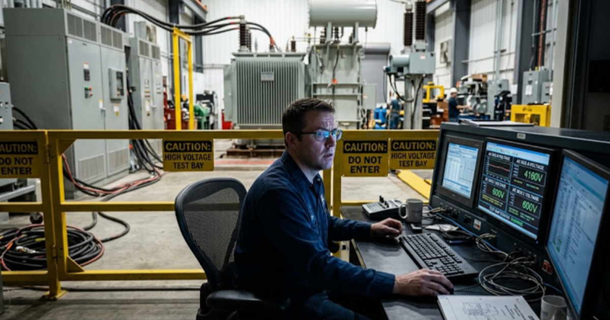
Real power exchange creates failure modes no offline model flags. Constant power loads on the DC bus present negative incremental impedance, the interlinking converter’s output impedance interacts with that, and the pair oscillates at a frequency neither subsystem shows alone. You only see it once current actually flows.
A 400 V DC bus feeding point-of-load converters is the familiar case. Each downstream converter regulates its output tightly, so as bus voltage sags it draws more current, sagging the bus further. Add a slow outer voltage loop on the interlinking converter and the DC section develops a low-frequency oscillation sitting where the AC droop response lives.
Sub-synchronous interaction belongs to the same family. Weak-grid conditions push the phase-locked loop and the current controller into a region where they reinforce each other, and the oscillation rides across the interface into the DC bus. Both get missed because the test that shows them needs power the signal-level bench doesn’t have.
“Both get missed because the test that shows them needs power the signal-level bench doesn’t have.”
What disciplined interface testing earns your team over time
Hybrid AC-DC microgrids don’t fail at their sources or their loads. They fail at the boundary between buses, inside the converter satisfying two sets of regulation rules at once. Proving that boundary at power, before commissioning, separates a project that starts cleanly from one spending its first year chasing oscillations.
Every hour spent proving the interlinking converter against realistic impedances buys back days of field debugging. Teams that get this right treat the interface as its own subsystem with its own acceptance criteria. They run the weak-grid case, the constant power load case and the fault ride-through case at full power, before the converter ships.
That’s what a power-level bench exists for, and it’s why OPAL-RT builds its PHIL systems so AC and DC nodes are energized in the same run instead of separate campaigns. A hybrid microgrid’s behaviour lives in the exchange between its buses. Get that exchange right on a bench and the rest of the design has room to be ordinary.

Power Electronics
09 / 30 / 2026
FPGA simulation for power electronics and motor drives
A technical comparison of CPU and FPGA solver architectures for power electronics and motor drive simulation, covering the timestep each reaches and how to split a model between them.
Power Electronics
09 / 29 / 2026
How to model and control a T-type three level inverter
An engineering overview of the T-type three level inverter leg, covering how it reaches three voltage levels, where device stress lands, and how neutral point balancing and modulation shape control.
Simulation
09 / 28 / 2026
How CHIL signal-level testing validates embedded controllers
A practical look at signal level controller hardware in the loop testing, covering I/O ranges, sensor emulation, latency and the setup checks that make embedded controller results trustworthy.