
Key Takeaways
- Define faulted-operation targets first, especially minimum torque, allowed ripple, and mission time, then pick phase count that can meet them with margin.
- Compare multiphase and three-phase choices using fault behaviour and verification scope, not peak performance, since isolation, thermal limits, and stable degraded modes set the true reliability ceiling.
- Lock motor, inverter, controls, and test strategy as one package so redundancy gains are provable, repeatable, and maintainable across the full safety case.
Choose motor phase count based on how much torque loss you can accept during faults.
Motor-driven systems use about 70% of industrial electricity in the United States, so a motor trip or a derate often shows up as lost output and missed schedules. High reliability drives start with a clear definition of what “still works” means after a fault. That definition will shape the motor, inverter, controls, and test plan long before hardware arrives.
Multiphase vs three phase motor selection is less about peak performance and more about controlled degradation. A three-phase machine can be extremely reliable when the system tolerates a shutdown and restart. A multiphase machine earns its keep when you must keep torque, speed, or controllability after one electrical failure.
Start with reliability targets and allowable torque loss
Set a faulted-operation target in measurable terms, then map it to phase count. Start with the minimum torque and speed you must hold after a single fault, the maximum time you must hold it, and the thermal headroom you can spend doing it. Those three values will quickly separate “ride-through” designs from “safe stop” designs.
Write the target in requirements that a test bench can pass or fail. You’ll want clear numbers for steady torque, torque ripple limits, and restart time, plus what “fault” means in your safety case. If you can accept a controlled stop, three-phase is usually the simplest path. If you must keep operating, multiphase becomes easier to justify because the redundancy is built into the torque production.
“Multiphase vs three phase motor selection is less about peak performance and more about controlled degradation.”
8 criteria for choosing multiphase or three-phase motors

1) Open circuit fault tolerance and remaining torque capability
An open phase is the cleanest fault to reason about, and it often becomes the benchmark for “keep running” claims. A three-phase motor will lose a large share of its torque and will heat unevenly if you try to carry load on two phases. A multiphase motor spreads torque across more phases, so losing one phase will leave a higher usable torque fraction and a smoother derate. A concrete case helps when you set targets, such as an aircraft electromechanical actuator that must hold position and still move at reduced rate after a single-phase open. The value is not magic torque, it is controlled torque with predictable limits that you can certify and test.
2) Short circuit behavior and options for fault isolation
A shorted phase is harder than an open because current can rise fast and the fault can couple into neighbouring phases. Three-phase systems typically rely on fast current limiting, shutdown, and isolation at the inverter or upstream protection. Multiphase gives you more ways to re-route torque production, but only if the design includes a clear isolation method so the shorted path stops dominating loss and heat. Pay attention to where isolation occurs, at the motor terminals, in the inverter, or through contactors, and how quickly it acts. The best choice is the one with a defined safe response time and a known post-fault operating point. If isolation is slow or uncertain, added phases will not rescue the system.
3) Torque ripple, vibration, and acoustic limits under faults
Faulted operation can meet torque and still fail your system if ripple and vibration spike. Two-phase conduction in a three-phase machine can produce strong pulsating torque, which transfers directly into gears, couplings, and mounts. Multiphase control can shape the remaining phase currents to reduce ripple, but you must validate that behaviour over speed and load, not just at one operating point. Vibration matters because it compounds existing mechanical risks, and bearings are often the first to pay the price. Bearing-related issues account for about 51% of induction motor failures in a commonly cited field survey analysis. If your reliability case is tight, treat ripple control as a primary requirement, not a tuning detail.
4) Inverter leg count, gate drive risk, and parts count
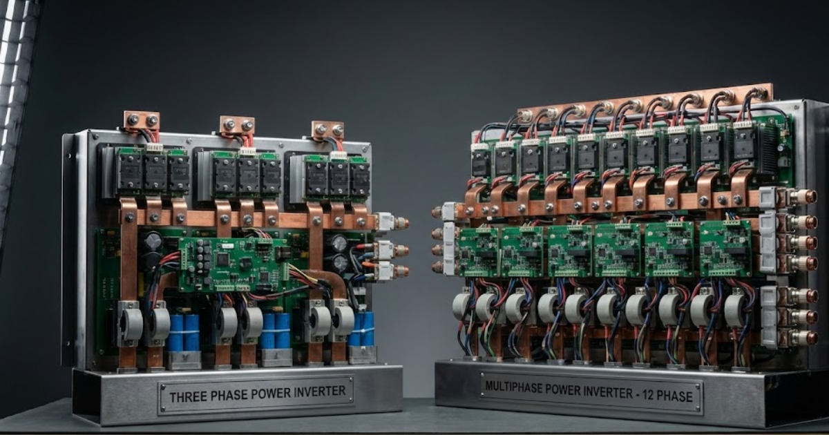
More phases usually means more inverter legs, more gate drivers, more current sensing, and more interconnects. That extra hardware can raise fault coverage options, but it also raises parts count and test scope. Three-phase inverters are mature, compact, and widely supported, which lowers integration risk and simplifies spares. Multiphase inverters demand a deliberate approach to single-point failures, such as how a gate driver fault behaves and how you detect it before it becomes a destructive event. Look for architectures that fail to a known state, not just “off.” The practical trade is clear: multiphase buys electrical redundancy, while three-phase buys hardware simplicity and proven supply chains.
5) Control complexity, sensing needs, and safe degraded modes
Phase redundancy only helps if the control system can use it safely. Three-phase control is well understood, and safe stop behaviour is straightforward to implement and verify. Multiphase control adds current allocation choices, fault detection logic, and degraded-mode behaviour that must remain stable under sensor errors and timing jitter. Your sensing plan matters as much as the algorithm, since losing a current sensor can look like losing a phase if you haven’t designed for it. Define degraded modes explicitly, including what you will stop controlling, what you will clamp, and what you will keep regulating. The more complex the degraded mode, the more you should invest in automated regression testing and fault injection.
6) Efficiency, copper loss, and thermal margin at high load
High-reliability designs usually run with thermal headroom, and phase count shapes how you spend it. A multiphase winding can reduce per-phase current for the same power, which can help with conductor sizing and hotspot control, but total copper loss still depends on how you distribute current and how the winding is built. Three-phase machines often win on simplicity and optimized manufacturing, which can translate to high baseline efficiency and predictable thermal models. The key check is faulted thermal behaviour, not just nominal efficiency. If you must keep operating after a phase loss, confirm that remaining phases will stay inside insulation limits for the full mission time. Heat, not torque, often becomes the limiting factor in degraded operation.
7) EMI, harmonics, and filter sizing for compliance testing
Phase count changes your switching pattern options, and that changes conducted and radiated noise. Three-phase drives have well-known filter approaches, while multiphase systems can introduce additional harmonic content if the switching strategy is not planned around compliance limits. More inverter legs also means more edges and more coupling paths, which can complicate grounding and cable layout. You should treat EMI as a system property that includes the motor, inverter, harness, and enclosure, not a late-stage filter problem. If compliance testing is a schedule risk, the conservative choice is the architecture with the smallest unknowns in switching behaviour and cable coupling. Multiphase can still pass cleanly, but it will require disciplined layout rules and early measurements.
8) Verification effort including HIL coverage and safety case needs
The engineering cost difference often shows up in verification, not in hardware. Three-phase fault handling can be validated with a smaller set of scenarios because the degraded states are fewer and easier to bound. Multiphase fault tolerance increases the number of states you must test, since you’re validating continued operation across different failed phases, sensors, and switching devices. Hardware-in-the-loop testing becomes more important because you need repeatable fault injection without risking prototypes, and timing details will matter in current limiting and mode switching. Teams often use OPAL-RT real-time simulation to run those fault campaigns early and keep the control software consistent as hardware changes. If your safety case demands proof of controlled degraded operation, plan for verification effort as a first-class requirement, not a downstream task.
| Criterion | What you learn from it |
|---|---|
| 1 Open circuit fault tolerance and remaining torque capability | You’ll know how much torque remains after one phase opens. |
| 2 Short circuit behaviour and options for fault isolation | You’ll confirm isolation speed and safe post-fault operation. |
| 3 Torque ripple, vibration, and acoustic limits under faults | You’ll see if degraded torque creates damaging vibration. |
| 4 Inverter leg count, gate drive risk, and parts count | You’ll weigh redundancy against parts and failure points. |
| 5 Control complexity, sensing needs, and safe degraded modes | You’ll judge if controls stay stable under faults. |
| 6 Efficiency, copper loss, and thermal margin at high load | You’ll learn if heat limits faulted operation time. |
| 7 EMI, harmonics, and filter sizing for compliance testing | You’ll estimate compliance risk from switching and cabling. |
| 8 Verification effort including HIL coverage and safety case needs | You’ll size the test campaign needed for safety evidence. |
“Treat phase count, inverter architecture, and fault test coverage as one package, or you’ll pay later in rework and late surprises.”
Match motor phases, inverter design, and test strategy
The best reliability choice is the one you can specify, build, and prove under faults with tight bounds. Three-phase is the clean fit when your system can tolerate a stop, restart, or switchover, because the hardware and verification paths are well traveled. Multiphase is the clean fit when you must keep controlled torque after a single electrical fault, because redundancy is inherent but the verification work will be heavier. Treat phase count, inverter architecture, and fault test coverage as one package, or you’ll pay later in rework and late surprises. OPAL-RT fits naturally when you need repeatable fault injection and timing-accurate closed-loop validation before the full power stage is locked.
Real-time solutions across every sector
Explore how OPAL-RT is transforming the world’s most advanced sectors.

Industry applications, Simulation
03 / 31 / 2026
Managing high-frequency switching in real-time EMT simulation
Precision in testing complex power systems is essential to avoid failures, accelerate innovation, and integrate new technologies safely.

Simulation
03 / 30 / 2026
Understanding timestep requirements for modern power converters
Practical criteria for selecting EMT and real time simulation timesteps for power converters, covering switching resolution, control and PWM timing alignment, multirate approaches, and verification checks.

Energy, Industry applications, Simulation
03 / 29 / 2026
Validating data center energy management systems using real-time HIL
This piece explains how AI workload variability affects data centre power stability and how closed-loop HIL testing helps validate EMS control behaviour under site and grid stress.
EXata CPS has been specifically designed for real-time performance to allow studies of cyberattacks on power systems through the Communication Network layer of any size and connecting to any number of equipment for HIL and PHIL simulations. This is a discrete event simulation toolkit that considers all the inherent physics-based properties that will affect how the network (either wired or wireless) behaves.