When to use CPU or FPGA for real-time simulation
Industry applications, Simulation
03 / 19 / 2026
Key Takeaways
- CPU and FPGA should be chosen from timing needs and model structure, not from a generic preference for more hardware.
- Fast switching sections belong on FPGA hardware, while broader plant models usually belong on CPU execution.
- Hybrid architecture gives you the strongest balance of fidelity, scale, and test efficiency when the partition is planned carefully.
Choose an FPGA when switching events, protection logic, or pulse timing must be resolved at sub-microsecond scale. That split matters more each year as electrified systems get more complex and test benches have less room for error. Electric car sales exceeded 17 million globally in 2024, which means more inverter, charger, and motor control designs are moving through validation pipelines that depend on accurate real-time testing.
“Choose a CPU when your model is large, electrically broad, and tolerant of microsecond-level steps.”
Teams run into trouble when they treat CPU and FPGA as interchangeable compute options. They are different execution models with different strengths, limits, and cost profiles. Good architecture choices come from matching timing needs, model structure, and I/O requirements to the right processing path, then keeping only the fastest physics where the fastest hardware is actually needed.
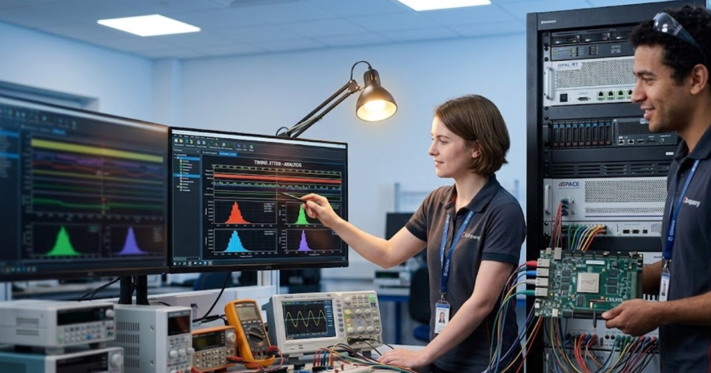
Real-time simulation performance depends on computation architecture choices
CPU and FPGA selection is mainly a timing and model-structure choice, not a branding or preference choice.
A CPU excels when your plant model includes large networks, slower electromechanical dynamics, and many elements that can share a larger fixed step. A grid study with feeders, transformers, machines, and supervisory controls usually fits that profile. An FPGA becomes the right option when the simulation must resolve switching edges, dead time, PWM interaction, or nanosecond-scale protection behaviour that a sequential processor will not hold deterministically.
That distinction matters because real-time execution fails at the point where computation time exceeds the assigned step. Once that happens, the model stops being a faithful stand-in for hardware. You start debugging a timing problem instead of the system itself. The safest choice is rarely the fastest possible hardware everywhere. The safest choice is the architecture that matches the fastest behaviour that must be represented, then leaves everything slower on the more flexible platform.
CPU-based simulation fits large system models with moderate switching dynamics
CPU-based simulation is best when you need model size, solver flexibility, and easier iteration more than extreme time resolution.
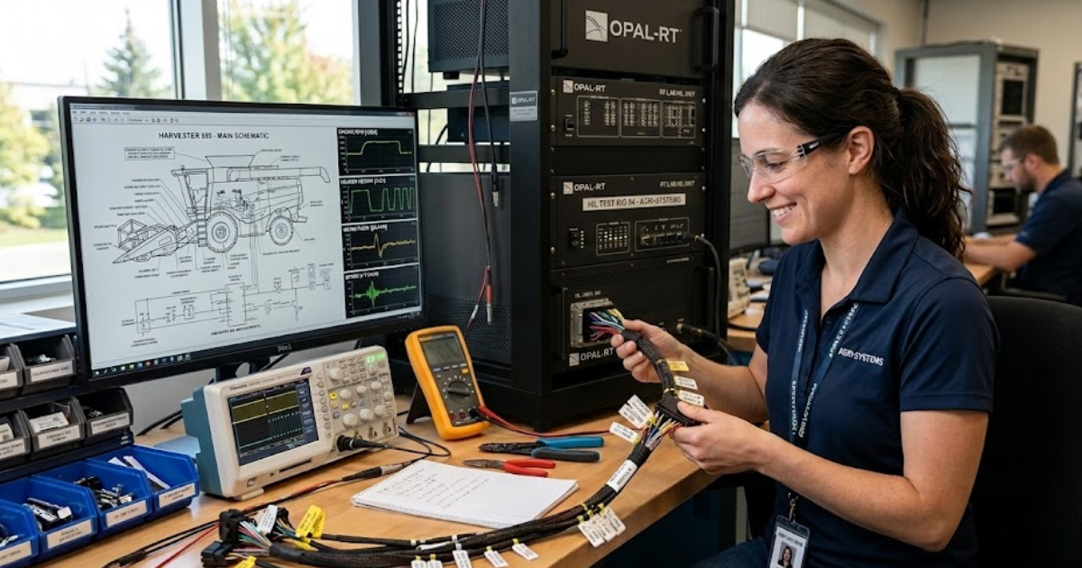
A protection study for a microgrid controller is a good example. You might need feeders, sources, breakers, transformers, and machine models, but you do not need to resolve every switching event inside each converter at nanosecond scale. A CPU can handle that broader system view with practical time steps and easier model updates. The case study with Harvest shows this clearly. The rectifier side of a medium-voltage drive used slower switching, so a time step in the tens of microseconds was sufficient, making CPU execution the cost-conscious choice for that portion of the model.
You should also favour CPU execution when the test workflow changes often. Controls teams usually need fast edits, repeated parameter sweeps, and easier access to large libraries of system components. Those tasks matter in early validation, where model coverage is often more important than switch-level detail. CPU capacity is limited, but it is usually the right place to start when your model is broad and your timing target is measured in microseconds, not nanoseconds.
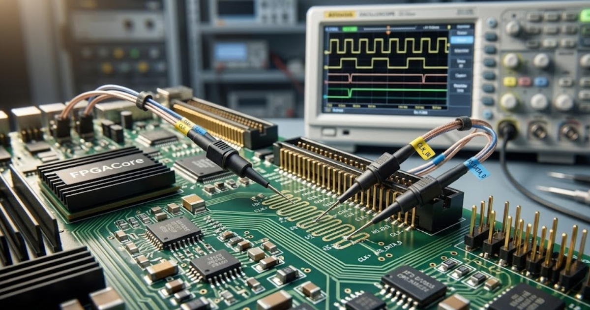
FPGA-based simulation supports nanosecond time steps and high switching frequency models
FPGA-based simulation is the right choice when your model must execute with highly deterministic timing at very small steps.
A power converter HIL bench is the clearest case. If your controller reacts to carrier-level PWM behaviour, dead-time effects, or fast fault transitions, a CPU will not hold the same timing certainty as dedicated hardware logic. The uploaded drive example notes FPGA execution for power electronics models with switching frequencies above 200 kHz and time steps as small as the nanosecond level. That is exactly the territory where FPGA use stops being optional and becomes necessary.
The tradeoff is development discipline. FPGA resources are finite, and detailed switching models consume them quickly. You need tighter partitioning, clearer signal planning, and a good understanding of what behaviour must remain explicit. That effort pays off when your controller under test is sensitive to the exact order and timing of electrical events. FPGAs are not simply faster CPUs. They are better suited to repeated parallel operations that must happen at precise intervals with very little timing variation.
Power electronics switching behaviour often determines when FPGA becomes necessary
Switching behaviour is usually the first technical signal that tells you a CPU-only model will miss important events.
Consider a cascaded medium-voltage drive. The Harvest success story describes single full-bridge submodules switching at 500 to 1000 Hz, while phase shifting and PWM dead time push overall per-phase switching behaviour to as high as 10 kHz. That same model included 24 three-phase full-bridge modules, 72 transformer-to-rectifier connections, and up to 96 switches. A CPU may still simulate parts of that system, but the switching-rich sections are where timing pressure builds fast.
That pressure is not limited to drives. The same pattern appears in traction inverters, battery test rigs, grid-forming converters, and fast charger validation. Once your controller decisions depend on edge timing rather than averaged electrical response, small timing errors stop being harmless. Global electricity demand rose an estimated 4.3% in 2024, adding pressure on engineers to validate more converter-heavy systems with higher confidence. That is one reason switching fidelity has moved from a specialist concern to a routine architecture filter.
Model partitioning strategies that combine CPU and FPGA execution effectively
Hybrid execution works best when the FPGA handles fast switching domains and the CPU handles slower electrical and system-level dynamics.
A medium-voltage drive offers a practical template. The inverter and motor-side power electronics can stay on the FPGA, where switching resolution and deterministic I/O matter most. The transformer, rectifier, supervisory logic, and wider plant context can remain on the CPU if their dynamics fit larger steps. The slower rectifier section stayed on the CPU, while high-speed converter behaviour was assigned to FPGA execution.
Good partitioning follows a short set of rules:
- Put carrier-level switching and fast protection paths on the FPGA.
- Keep broad electrical networks and slower plant dynamics on the CPU.
- Cross the CPU and FPGA boundary only where signals change slowly enough.
- Minimize back-and-forth coupling that forces tight synchronization overhead.
- Test timing margins early with open-loop execution before controller integration.
Partitioning is not just a compute decision. It shapes model credibility. A poor split creates interface bottlenecks, artificial delays, and debugging work that hides the actual control problem. A disciplined split turns hybrid architecture into a clear engineering advantage.
| Architecture choice | What it is best suited for | Main limitation you must plan around |
| CPU-only execution | Large electrical systems with moderate dynamics and frequent model edits | Time-step limits will hide fast switching detail and edge timing |
| FPGA-only execution | Converter-dense benches where deterministic sub-microsecond behaviour is required | Resource limits make very large full-system models harder to keep detailed |
| Hybrid CPU and FPGA execution | Mixed systems where only part of the model needs very fast timing | Poor partitioning will create synchronization overhead and weak interfaces |
| CPU for plant and FPGA for converter | Controller testing where plant context matters but switching must remain explicit | Boundary signals must be chosen carefully to avoid artificial coupling errors |
| CPU for early work and FPGA for late validation | Teams that want quick model iteration first, then deeper timing accuracy later | Rework appears if model structure was not prepared for later partitioning |
Cost, scalability, and integration constraints that shape architecture decisions
Architecture choice should follow the cheapest setup that still preserves the behaviour you must trust.
A lab testing one motor controller across many operating points usually gets better value from a CPU-heavy setup first. You can build the surrounding plant, exercise the controller I/O, and refine corner cases without filling expensive fast hardware with model detail that adds little value.
Scalability also matters. Once you move to larger converter counts, more sensors, or dense I/O requirements, the question shifts from raw compute to system packaging. Optical links, synchronized expansion, and modular I/O start to matter as much as solver choice. That is where platform design becomes part of architecture design. OPAL-RT systems are often used in this kind of workflow because teams need CPU, FPGA, and I/O growth in the same test path, not as separate decisions. The useful lesson is broader than any one platform. You should treat architecture, I/O, and synchronization as one design problem from the start.
Common modelling mistakes that cause CPU simulations to miss real-time deadlines
CPU simulations miss deadlines when the model keeps too much fast detail in places that do not belong on a sequential solver.
A common mistake appears in converter studies that import offline models directly into real-time work. The model keeps every switching device explicit, retains unnecessary coupling across subsystems, and uses one aggressive time step for everything. That looks rigorous, but it usually produces overruns. Another frequent mistake is tying high-speed converter sections too tightly to slower networks, which forces the whole model to run faster than needed.
The slower rectifier section stayed on the CPU, while more demanding switching behaviour moved elsewhere. It also relied on solver partitioning to decouple more than twenty converters from a multi-winding transformer so the model could meet real-time timing constraints. You should take the same approach in your own work. Strip out unnecessary detail, separate fast and slow domains early, and test timing margins before declaring the model ready for HIL.
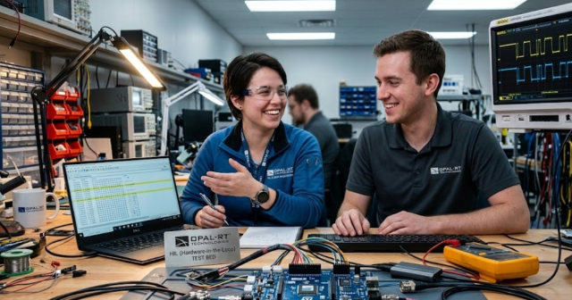
Hybrid CPU and FPGA platforms provide scalable performance for complex HIL testing
“Hybrid platforms are the best long-term choice for complex HIL when only part of the system needs extreme timing fidelity.”
That judgement comes from execution, not theory. Most advanced benches contain a mix of slow and fast physics, broad plant context, and controller-facing I/O that must stay believable under fault cases. A pure CPU approach runs out of timing headroom. A pure FPGA approach becomes expensive and rigid if you force the whole plant into hardware logic. Hybrid architecture solves that problem when the split is disciplined and the interfaces are clean.
One bench supported multiple motor types, fault conditions were reproduced safely, and control issues were exposed earlier in development. That is the result you should aim for. OPAL-RT fits naturally into that closing picture because its work in CPU and FPGA co-execution reflects how strong labs already build serious test systems. Good real-time simulation is not about picking one processor and hoping for the best. It is about matching each part of the model to the hardware that will execute it faithfully.
Real-time solutions across every sector
Explore how OPAL-RT is transforming the world’s most advanced sectors.
Simulation
03 / 25 / 2026
Integration testing between firmware and physical interfaces
Covers how to plan and run firmware integration testing for physical interfaces using staged loops, HIL protocol simulation, tool selection, and trace-based debugging for CAN and similar buses.
Industry applications, Simulation
03 / 25 / 2026
Real-time simulation of multilevel converters and cascaded topologies
A practical guide to multilevel converter simulation that explains how cascaded H bridge models are partitioned across CPU and FPGA resources for accurate real-time EMT and hardware in the loop testing.
Simulation
03 / 23 / 2026
Scaling from academic HIL setups to industrial validation platforms
Practical guidance for moving an academic HIL system from an entry level FPGA real time simulator to a modular platform that supports scalable real time simulation, repeatable tests, and traceable industrial validation results.
EXata CPS has been specifically designed for real-time performance to allow studies of cyberattacks on power systems through the Communication Network layer of any size and connecting to any number of equipment for HIL and PHIL simulations. This is a discrete event simulation toolkit that considers all the inherent physics-based properties that will affect how the network (either wired or wireless) behaves.