7 Top power electronics simulation tools for engineers
Power Electronics
12 / 16 / 2025

Key Takeaways
- Careful selection of power electronics simulation tools helps engineers cut project risk, shorten lab debugging, and protect schedules.
- No single platform serves every use case, so teams benefit from a toolkit that spans offline simulation, real-time targets, and hardware-in-the-loop setups.
- Software for power electronics improves modelling quality, strengthens collaboration between power and control engineers, and supports structured reuse of validated models.
- Real-time simulation, HIL, and modular interface hardware give firmware teams a safe, repeatable way to exercise controllers across fault cases and corner conditions.
- Open, standards-based integration and Python workflows turn simulation into a repeatable engineering process rather than isolated, one-off studies.
Power electronics engineers know that choosing the right simulation tool can save months of trial and error in the lab. When switching devices push into hundreds of kilohertz and control loops run on tight budgets, guesswork becomes expensive. Teams that invest in accurate, real-time capable modelling see fewer surprises when hardware finally powers on. The right mix of software and hardware support turns simulation from a checkbox into a source of confidence.
Project schedules rarely slip because engineers are lazy; they slip because systems behave differently than expected under stress. Detailed, well-structured simulation exposes those gaps early, especially for converters, inverters, and complex multi-converter systems. Careful selection of power electronics simulation tools is now as important as choosing devices or magnetics. Engineers who treat simulation as part of the main design loop, not an afterthought, gain a clear edge in schedule, cost, and technical quality.
How engineers compare software for detailed power electronics studies
Power electronics specialists usually start from the physics of the problem, not from a software brochure. The first filter is almost always fidelity around switching events, including how the solver treats discontinuities, snubbers, and non-linear devices. Engineers look closely at supported device models, numerical methods, and practical step sizes they can achieve on typical hardware. Only after that do questions about licences, support, and integration with other tools come into play.
Once basic accuracy is acceptable, the focus moves to workflow and risk. Engineers ask how easily they can carry the same plant model from desktop study to real-time target, then to hardware-in-the-loop (HIL) and lab tests. Teams compare scripting options, automation features, and integration with source control to assess how simulation fits into their existing development flow. The best software for power electronics is the one that fits the project constraints while still leaving room for future complexity.
7 power electronics simulation tools supporting accurate and efficient design
Engineers rarely rely on a single platform for every task, from early concept checks to final controller validation. Different stages favour different mixes of offline solvers, real-time targets, and HIL infrastructure. Real-time control design needs deterministic timing and tight I/O, while root cause analysis may rely on heavy offline runs and detailed component models. Power electronics simulation tools cluster into a few practical categories that map cleanly to these engineering needs.
Summary of key simulation tool categories
| # | Tool focus | Typical role in power electronics projects | Ideal for |
| 1 | FPGA-based solver | High-speed switching and detailed EMT behaviour in real time | Converter and inverter switching studies, protection checks |
| 2 | Real-time control prototyping platform | Rapid controller development with physical I/O | Control design and tuning before custom hardware is ready |
| 3 | CPU-based transient simulation engine | Complex multi-converter and system-level studies | Microgrids, multi-terminal converters, long-duration events |
| 4 | Real-time software suite | Orchestration of models, targets, and test workflows | Lab coordination and multi-user simulation setups |
| 5 | Hardware-in-the-loop system | Closed-loop validation of firmware and embedded controls | Safety-critical control testing and coverage expansion |
| 6 | Modular interface hardware | Electrical and signal connection between controllers and simulators | Reconfigurable benches, sensor and actuator emulation |
| 7 | Multi-domain simulation toolbox | Cross-domain and scripting-based studies across tools | Co-simulation, automation, and advanced integration with Python |
1. FPGA-based power electronics solver for high-speed switching studies
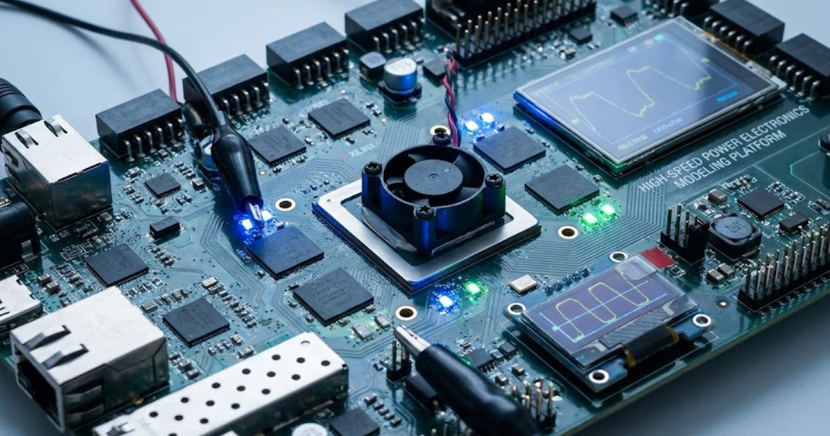
FPGA-based solvers give engineers the time resolution needed to study power stages with very fast switching without sacrificing real-time execution. These solvers run detailed electromagnetic transient models using tiny time steps, often in the sub-microsecond range, so gate transitions, dead time, and device dynamics are resolved cleanly. Instead of averaging switching behaviour, engineers can observe device currents, dv/dt, and circulating currents directly, even when multiple converters interact. This level of detail is extremely helpful when qualifying new devices, topologies, or protection strategies.
You can think of this type of tool as a bridge between rigorous offline simulation and physical hardware. Engineers use it to verify that modulation schemes, protection thresholds, and filter designs behave properly before any power stage is energised. A strong FPGA-based solver also supports convenient model creation, parameter management, and clear diagnostics when numerical limits are reached. For many teams, this category represents the best power electronics simulator when accurate switching behaviour is the highest priority.
2. Real-time control prototyping platform for converter and inverter development
Control engineers often want to validate new algorithms long before a final controller board exists. A real-time control prototyping platform gives them a target with fast I/O, deterministic scheduling, and ready integration with desktop modelling tools. Control code can be generated automatically from graphical models or written by hand, then deployed to run at kHz rates against either simulated or physical plants. This approach reduces the number of surprises when firmware moves to custom embedded hardware later in the project.
Engineers also appreciate the flexibility of reconfiguring I/O, communication buses, and execution rates as requirements change. A good platform lets you measure execution time, adjust task priorities, and log internal variables with minimal friction. This style of real-time prototyping gives insight into how your control structure behaves under delays, quantisation, and sensor noise. Teams that pair this tool with strong plant models gain a continuous thread from concept control diagrams to production-ready firmware.
3. CPU-based transient simulation engine for complex multi-converter systems
Large systems such as microgrids, offshore connections, or multi-terminal converter stations still rely heavily on CPU-based transient simulation. These engines handle dozens or hundreds of converters, long cables, transformers, and protection devices within a single coherent model. Engineers use them to study start-up sequences, fault propagation, and interaction between different control layers over long time spans. Variable step solvers and advanced numerical techniques help maintain accuracy without excessive run time, even when models are stiff.
Careful scenario definition within such tools lets you sweep parameters, fault locations, and control settings to understand margins. Many engines provide scripting interfaces for automation, batch runs, and custom measurements. When selecting this category of simulator, engineers pay attention to support for electromagnetic transient methods, parallel processing options, and import from existing design tools. This type of software for power electronics is often the backbone of system-level studies long before any lab hardware is available.
Power electronics engineers know that choosing the right simulation tool can save months of trial and error in the lab.
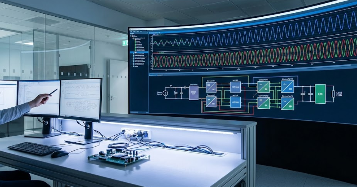
4. Comprehensive real-time software suite for model execution and test workflows
Real-time hardware loses much of its value without a strong software suite that manages models, I/O, and test configurations. A comprehensive real-time software platform helps engineers compile plant and control models, map signals to physical channels, and start or stop runs with predictable procedures. The same software often provides monitoring dashboards, logging, scripting interfaces, and integration with supervisory test tools. This reduces the number of manual steps and keeps test benches consistent across different projects and teams.
Strong suites also provide support for open standards like Functional Mock-up Interface (FMI), as well as integration with modelling tools and Python-based automation. Engineers look for features such as scenario management, user access control, and clear tracking of which model version ran on which hardware. These capabilities matter when safety audits, certification activities, or peer reviews ask for precise evidence. While this category may not be a simulator in itself, it shapes how reliably you can use the best power electronics simulator in your lab.
5. Hardware-in-the-loop system for validating control firmware and embedded designs
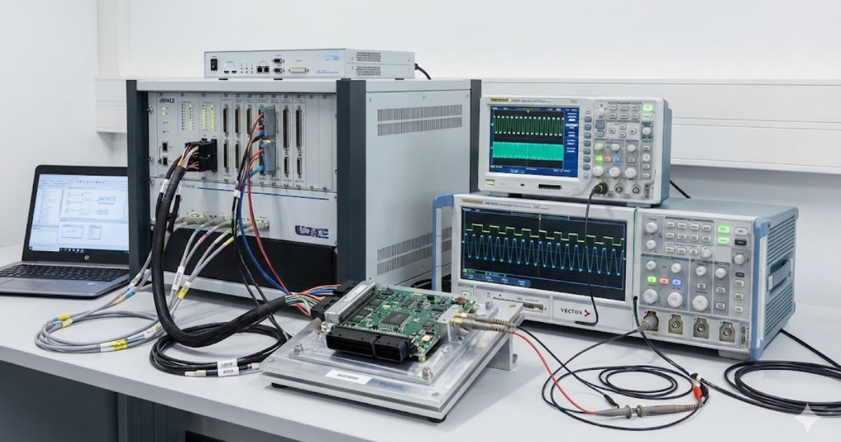
Hardware-in-the-loop (HIL) platforms connect embedded controllers to simulated plants so engineers can test firmware under harsh and unusual scenarios safely. The power stage, grid, or vehicle is represented by real-time models, while the controller under test uses exactly the same interfaces it will see in the lab or field. Engineers use HIL to run fault cases, corner conditions, and long-duration endurance tests that would be risky or expensive with hardware. This greatly increases test coverage before first power-up of actual converters or inverters.
Latency, jitter, and signal fidelity are key selection criteria for HIL systems in power electronics. The closed-loop delay must stay within the control budget to keep behaviour close to what you expect with hardware. Engineers also value flexible analogue and digital I/O, fault injection capabilities, and simple ways to adapt the test bench when hardware revisions appear. When these conditions are met, HIL often becomes the primary platform for validating new firmware releases and regression tests.
6. Modular power electronics interface for connecting controllers and external devices
Simulation is only as effective as the connections between the real-time target and external equipment. Modular interface hardware provides signal conditioning, isolation, and I/O configurations that match the needs of power electronics controllers. This can include analogue scaling to mimic sensors, digital I/O for gate signals, and support for communication protocols used in drives, converters, and grid equipment. A modular design lets engineers rearrange channels as projects and topologies change, instead of building a new custom rack each time.
Good interface systems also consider safety, maintainability, and clarity for lab users who move between benches. Teams appreciate clear labelling, swappable cards or modules, and wiring options that match the connectors on their controller hardware. Some platforms support current and voltage amplification to emulate sensors more realistically, or provide relay outputs for protection and interlocks. When interface hardware is flexible and robust, engineers spend more time running meaningful tests and less time rewiring racks.
7. Multi-domain simulation toolbox supporting FMI, Python, and model-based integrations
Power electronics designs live inside larger systems that include mechanics, thermal behaviour, communication networks, and operator interfaces. A multi-domain simulation toolbox helps engineers connect their converter and inverter models with these surrounding subsystems. Support for standards like Functional Mock-up Interface (FMI) allows plant and controller models to move between tools without rework. Python integration gives teams a way to automate studies, apply optimisation methods, or post-process data with custom analytics.
This category is particularly valuable for engineers who need to combine high-fidelity electrical models with control, mechanical, or thermal models from other groups. You can orchestrate co-simulation between tools, drive parametric sweeps, and feed results into custom design workflows. Strong support for scripting and open interfaces reduces dependence on any single proprietary format. When used with the right solvers, this toolbox turns a power electronics simulator into part of a broader, connected engineering process.
Engineers looking for the best power electronics simulator rarely find a single product that covers every need perfectly. Instead, they assemble a toolkit that spans FPGA-based solvers, real-time control prototyping, offline CPU engines, and HIL platforms. Clear categories, like the ones described here, help teams map project requirements to concrete simulation capabilities. Thoughtful selection across these categories gives you a simulation stack that supports accurate design, confident testing, and smoother handoff to hardware.
How software for power electronics improves modeling quality and workflow
Many teams start with simulation just to verify basic converter operation, then quickly realise how much it can improve quality across the whole project. Strong software for power electronics pushes modelling accuracy higher, supports collaboration between power and control engineers, and reduces risk when hardware shows up. When simulation is integrated into everyday work instead of used only at the end, engineers catch more issues while they are still cheap to fix. The effects show up in better performance, shorter debugging sessions, and fewer surprises in the lab.
- Higher-fidelity device and switching models: Accurate models of devices, magnetics, and parasitics help predicted waveforms line up with measurements. Engineers can investigate snubber design, layout effects, and switching losses with much more confidence.
- Faster iteration from concept to controller testing: Real-time capable tools let a plant model follow the project from schematic to HIL without being rebuilt each time. Control engineers can start tuning algorithms against realistic models long before final hardware exists.
- Better alignment between power and control teams: Shared models and open interfaces reduce friction between groups working on hardware, firmware, and higher-level functions. Common simulation assets mean that changes are visible across the team instead of being buried in separate files.
- Earlier detection of integration issues: Scenario libraries and automated test scripts reveal problems around protection coordination, start-up sequencing, and communication failures. Many of these situations would be difficult or risky to reproduce on a physical test bench.
- Stronger traceability and documentation: Simulation software that tracks model versions, test cases, and results helps engineers justify design choices to auditors, partners, and internal reviewers. This traceability becomes especially important for safety-critical converters and inverters.
- Reuse of validated models across projects: Once a plant or subsystem model is validated against measurements, teams can reuse it across new platforms or ratings. That reuse shortens design cycles and keeps expertise inside the organisation instead of scattered across individual spreadsheets.
Careful investment in simulation tools turns modelling from a one-off activity into a trusted reference for design and test.
Engineers gain a clearer picture of how control changes affect power-stage stress, and how component choices affect efficiency or thermal limits. This broader perspective helps teams make better trade-offs between cost, performance, and risk. Over time, the impact shows up in stronger designs, fewer field issues, and more predictable schedules.
How OPAL-RT supports teams selecting the right simulation workflow
Engineering groups often arrive with a mix of models, custom test benches, and legacy tools that must keep working while new projects start. OPAL-RT focuses on helping teams connect these pieces into a coherent workflow rather than forcing a single rigid stack. The company’s real-time digital simulators combine CPU and FPGA resources so that detailed switching studies, HIL scenarios, and system-level transients can share common hardware. This flexibility lets power electronics engineers choose the right level of detail for each project phase while keeping a consistent lab setup.
OPAL-RT also invests heavily in open integration with modelling tools, scripting through Python, and support for standards such as FMI, so existing assets can move into real-time workflows with minimal friction. Teams can start with control prototyping or HIL on a single bench, then scale to multiple racks as projects grow, all while using the same core software suite for configuration and test orchestration. This approach helps engineers maintain traceability, reuse models across projects, and coordinate lab time efficiently. As a result, OPAL-RT becomes a trusted partner for teams that need reliable, real-time simulation at the centre of their power electronics development strategy.
Common Questions
How do I choose the best power system simulation software for my project?
Choosing the right tool depends on the type of studies you need, such as electromagnetic transient analysis, steady-state planning, or hardware-in-the-loop validation. You should compare solver methods, model libraries, and integration paths with your existing workflow. Real-time capability and hardware connections are key if your project requires closed-loop testing. OPAL-RT helps you match the right simulation approach with practical lab integration so you can move faster with less risk.
What’s the difference between offline and real-time power system simulators?
Offline simulators run detailed studies without time constraints, which makes them well suited for design and sensitivity analysis. Real-time simulators, on the other hand, execute models within strict time steps to stay synchronized with hardware and controllers. Both approaches often work best when paired, with offline studies guiding scenarios later tested in real time. OPAL-RT bridges this gap by supporting both offline modeling and real-time execution, giving you continuity across design and testing stages.
Why should I use hardware-in-the-loop for power system projects?
Hardware-in-the-loop (HIL) allows you to test controllers, relays, and converters against simulated grids before using live hardware. This approach improves safety, reduces test time, and exposes issues earlier when they are less costly to fix. With accurate models and tight timing, you can validate protections, controls, and fault cases with confidence. OPAL-RT offers purpose-built HIL platforms that give engineers a reliable way to test without putting equipment or schedules at risk.
Can power system modeling and simulation improve collaboration between my teams?
Yes, consistent simulation models serve as a shared reference across design, testing, and planning teams. When everyone works from the same data sets, it reduces duplication, errors, and misalignment between studies. Shared libraries and automation also make it easier to reproduce cases and track changes over time. OPAL-RT supports open standards and scripting so you can integrate across groups while keeping models transparent and traceable.
How can I future-proof my investment in simulation tools?
The most effective way is to choose platforms that are open, scalable, and adaptable to new standards. You want flexibility to run larger networks, add new device models, or connect emerging hardware without starting over. Cloud-ready and AI-compatible solutions also ensure you can extend capabilities as projects grow. OPAL-RT designs its platforms to scale with your requirements so you can be confident your simulation setup will remain relevant.
Real-time solutions across every sector
Explore how OPAL-RT is transforming the world’s most advanced sectors.

Industry applications, Simulation
03 / 31 / 2026
Managing high-frequency switching in real-time EMT simulation
Precision in testing complex power systems is essential to avoid failures, accelerate innovation, and integrate new technologies safely.

Simulation
03 / 30 / 2026
Understanding timestep requirements for modern power converters
Practical criteria for selecting EMT and real time simulation timesteps for power converters, covering switching resolution, control and PWM timing alignment, multirate approaches, and verification checks.

Industry applications, Simulation, Energy
03 / 29 / 2026
Validating data center energy management systems using real-time HIL
This piece explains how AI workload variability affects data centre power stability and how closed-loop HIL testing helps validate EMS control behaviour under site and grid stress.
EXata CPS has been specifically designed for real-time performance to allow studies of cyberattacks on power systems through the Communication Network layer of any size and connecting to any number of equipment for HIL and PHIL simulations. This is a discrete event simulation toolkit that considers all the inherent physics-based properties that will affect how the network (either wired or wireless) behaves.