
Key Takeaways
- Raising the bus to 800 VDC cuts current and copper at megawatt rack power, and it moves the hard problems into converter controls, protection and stability.
- DC faults have no zero crossing and rise within microseconds, so protection depends on solid state devices and on selectivity that magnitude alone can’t provide.
- The chain from utility connection to rack behaves as one coupled system, and it should be studied that way before equipment is ordered.
An 800 VDC feed lets a facility deliver a megawatt to a single AI rack with a fraction of the current, copper and conversion loss that low voltage distribution needs.
Moving the bus to 800 VDC shifts the hard engineering problems out of the busbar and into converter controls, fault protection and bus stability. Global data centre electricity use is set to more than double to around 945 TWh by 2030, and much of that growth sits in dense AI halls where the old distribution chain runs out of room.
The 800 VDC architecture is sound, but its behaviour is decided by how the converters interact, and that can’t be read off a single-line diagram. Teams that study the full chain from grid to rack as one coupled system will commission faster and with fewer surprises. Treating each stage as a separate purchase is where projects get into trouble.
What 800 VDC power distribution means for an AI data centre
800 VDC power distribution carries direct current at a nominal 800 volts from a facility-level conversion stage to the compute racks, replacing the low voltage AC feeds and in-rack rectifiers used today. Each rack then steps the bus down to the voltage its processors need.
Picture a hall where the utility arrives at medium voltage, a rectifier stage at the edge of the room produces the DC bus, and a busway runs it along each row. The rack no longer holds AC power supplies. It holds DC to DC converters, which leave more of the cabinet for compute. Rectification, storage and protection move upstream into shared equipment, so you’ll gain density and lose some of the isolation that separate supplies gave you.
Why AI racks are outgrowing low voltage AC distribution
AI racks are outgrowing low voltage distribution because current scales with power, and conductor loss scales with the square of current. A rack that draws ten times the power at the same voltage needs ten times the current, and its busbars dissipate one hundred times the heat.
Run the numbers on a 1 MW rack as a generic illustration. At a 54 V busbar, the rack pulls roughly 18,500 A, which no practical busbar carries without a great deal of copper. At 800 V the same megawatt needs 1,250 A, about one fifteenth of the current. For the same conductor resistance, conduction loss falls by a factor of more than 200. That’s why the voltage has to rise before the rack power does.
How power reaches an AI rack through solid state conversion
Power reaches an AI rack through three conversion steps in an 800 VDC design. Medium voltage AC from the utility is rectified to 800 VDC, a rack-level converter steps that down to an intermediate bus near 48 V or 12 V, and point-of-load regulators deliver less than 1 V to the processors.
A solid state transformer replaces the line frequency transformer and separate rectifier with power electronics that switch at medium frequency through a much smaller isolation transformer. It will regulate the DC bus actively, correct power factor and limit fault current, which a passive transformer can’t do.
Consider a campus fed at 13.8 kV or 34.5 kV. A conventional build uses a step-down transformer, AC switchgear and a large rectifier, while a solid state design folds those into cascaded converter modules. Both produce the same bus, yet they respond very differently to a voltage sag, a load step or a fault. Every stage is now a controlled converter with its own loop.
800 VDC compared with AC distribution inside the facility
The main difference between 800 VDC and AC distribution inside the facility is where rectification happens. AC distribution carries alternating current to each rack and converts it there, while 800 VDC converts once upstream and distributes direct current. That single choice moves cost, loss and risk from the rack to the row.
A row of twenty racks shows the trade. With AC, each rack carries its own rectifier shelves and a fault in one stays local. With a shared DC bus, twenty racks share one source and one fault path, so protection must isolate a single branch in microseconds while the others ride through.
| What you’re comparing | 415 V or 480 V AC distribution | 800 VDC distribution |
| Where AC becomes DC | Each rack rectifies its own feed. | One upstream stage rectifies for a whole row. |
| Current for a given rack power | High current forces thick conductors. | Higher voltage cuts current and copper. |
| How a fault is cleared | Breakers interrupt at a natural zero crossing. | Devices must force current to zero themselves. |
| What sets stability | Utility and transformer impedance dominate. | Converter control loops and bus capacitance decide. |
| Maturity of design practice | Coordination methods are well established. | Protection practice is still being written. |
AC gives you mature breakers and decades of coordination practice, and DC gives you density and fewer stages. Pick DC for dense AI halls, and budget engineering time for the protection and control study it requires.
DC fault protection works differently when current has no zero crossing
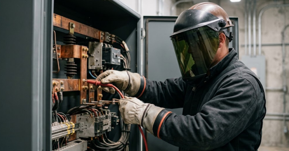
DC fault protection is harder than AC protection because direct current never passes through zero. An AC breaker waits for the next zero crossing to extinguish its arc, and a DC arc has no such moment. The protective device has to force the current down itself, before the bus capacitors empty into the fault.
“DC fault protection is harder than AC protection because direct current never passes through zero.”
Take a generic bolted fault on an 800 V bus with 10 microhenries of loop inductance. Current starts rising at 80 A per microsecond, so it climbs by thousands of amperes inside 100 microseconds. A mechanical breaker that opens in milliseconds is far too slow for that, which is why solid state circuit breakers are specified.
Once the capacitors have discharged, the upstream converter limits its output and fault current will settle near rated current. That’s too low for a downstream device to tell a fault from a heavy load on magnitude alone, so selectivity depends on rate of rise, direction and communication between devices.
Grounding adds one more choice. A midpoint-grounded bus at plus and minus 400 V halves the voltage to earth, and each grounding scheme alters what the relays see.
Constant power loads create stability limits on a DC bus
Constant power loads limit DC bus stability because they behave as a negative resistance to small disturbances. A rack converter regulates its output tightly, so when bus voltage dips it draws more current, which pushes the voltage lower still. Against a weakly damped source, the bus will oscillate.
A 1 MW load on an 800 V bus presents an incremental resistance of about minus 0.64 ohms, and the source converter must hold an output impedance well below that magnitude. AI training makes this harder, since thousands of processors step between idle and full power at the same instant. Engineers at OPAL-RT model these interactions on real-time simulators, where the physical controller runs against a simulated bus and its damping margin is measured directly.
Which parts of the 800 VDC chain to study first
Study the interactions first, since single components are well understood and the surprises live between them. Grid disturbances, control loops, protection timing and load steps all meet on the same bus.
Grid-side behaviour deserves an early place. During a 2024 transmission fault in Virginia, approximately 1,500 MW of data centre load dropped off the grid after site protection counted repeated voltage disturbances and moved to backup power. Nothing was broken inside those sites. Their settings did what they were told. These 5 studies will give you the most return for the least modelling effort.
- Ride-through of the front-end converter during utility voltage sags and reclosing sequences
- Bus voltage response to synchronized load steps from training workloads
- Fault current rise and clearing time for a fault at each branch
- Selectivity between solid state breakers during the current-limited phase
- Handover between grid supply, battery storage and backup generation
Proving the grid to rack chain before it is built
The 800 VDC chain is proven before it’s built when its converters, protection and loads have been exercised as one system under the faults and load steps they’ll meet in service. Component datasheets won’t give you that.
We’d rather see a protection engineer argue with a simulated fault in month 3 than with a physical one in month 30. A model of the full chain lets your team adjust a breaker setting or a control gain in an afternoon and see what it does to every other stage.
“Teams that do this work early won’t need luck at energization.”
That’s the discipline this architecture asks for. OPAL-RT already models data centre power systems in real time, so the path from the utility connection to the rack converter, including control behaviour and DC faults, can be studied long before equipment arrives. Teams that do this work early won’t need luck at energization. They’ll have seen the bad days already.

Automotive
10 / 21 / 2026
Megawatt charging system validation for heavy duty trucks
A practical look at how the megawatt charging system works, how it differs from CCS and how charger controls are tested before a truck site is energized.
Automotive
10 / 19 / 2026
Dynamometer testing and motor emulation compared for e-drive programs
A comparison of dynamometer testing and motor emulation for e-drive programs, covering what each method proves, what it costs and how teams sequence both.

Power Electronics
10 / 17 / 2026
How wide bandgap devices push converter power density
Wide bandgap devices raise converter power density through faster switching and smaller passives, and this guide traces that chain from device physics to thermal limits to validation.