Key Takeaways
- Model fidelity should match the validation question, since extra physics costs solver time without improving the answer you need.
- Equivalent circuit models predict what the battery management system sees, while electrochemical models predict what the cell does to itself.
- Ageing and thermal terms need re-anchoring against fielded measurements, or a bench-validated controller will report optimistic state of health.
A battery model earns its place in validation when it reproduces the exact behaviour your controller reacts to, and nothing more.
Teams building EV powertrains and teams building grid storage reach for the same tool set and then find the models don’t transfer. Global electric car sales exceeded 20 million in 2025, roughly one quarter of every new car sold, and each pack sits behind a battery management system somebody validated against a model. The pressure isn’t on model sophistication. It’s on picking the representation that answers the question in front of you at the speed your test bench runs.
Battery modelling splits into two families that answer different questions. Equivalent circuit models give you speed and a short parameterization path. Electrochemical models give you visibility into internal states no sensor reports. The judgment call is knowing which failure mode you’re chasing, because a model tuned for terminal voltage accuracy will mislead you the moment you ask about lithium plating.
What battery modelling means for EV and grid validation
Battery modelling is the practice of representing a cell or a pack with equations that predict voltage, current, temperature and state of health under a given load profile. The model stands in for physical hardware so control software can be exercised long before a production pack exists.
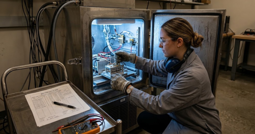
A BMS validation rig shows this clearly. The controller reads voltage and current, estimates state of charge, and decides when to limit power or open a contactor. Swap the physical pack for a model running at a 50 microsecond step and the controller can’t tell the difference, provided the model reproduces the signature it expects.
That substitution is the whole point. You get to run overcharge, cell imbalance and sensor dropout hundreds of times without consuming hardware. A model that reproduces terminal voltage validates a state of charge estimator competently and says nothing about how quickly a cell heats at 3C.
The main difference between equivalent circuit and electrochemical models
The main difference between equivalent circuit and electrochemical models is what they track internally. An equivalent circuit model reproduces the terminal behaviour of a cell using resistors and capacitors fitted to bench data. An electrochemical model solves the physics of lithium transport inside the electrodes and the electrolyte.
Across a two hour drive cycle at real time, a first-order equivalent circuit model with a series resistor, one RC branch and an open circuit voltage curve matches measured terminal voltage within a few millivolts across the usable state of charge band. A pseudo-two-dimensional model of the same cell resolves lithium concentration gradients across each electrode and predicts when anode surface potential drops low enough for plating to begin.
The circuit model tells you what the BMS will see. The physics model tells you what the cell is doing to itself. Teams get into trouble when they push a circuit model past the band it was fitted in and treat its output as evidence about cell safety.
“The circuit model tells you what the BMS will see. The physics model tells you what the cell is doing to itself.”
Selecting model fidelity for the validation question you have
Model fidelity should follow the shortest path to the answer you need. A controller timing test wants the simplest model that runs deterministically inside your solver step. A cell safety study wants resolution the circuit model can’t provide. Anything past that costs you solver time and parameterization effort with no return.
The tradeoff shows up plainly once you compare the options.
| Modelling approach | What it captures well | What it costs you |
| Internal resistance model | It reproduces terminal voltage under steady load without tuning. | It misses relaxation and drifts during transients. |
| First-order circuit model | It tracks voltage response across drive cycles in real time. | It needs lookup tables refreshed at every temperature. |
| Second-order circuit with thermal coupling | It captures fast and slow relaxation plus cell heating. | It doubles parameterization effort and solver load. |
| Single particle model with electrolyte | It exposes concentration limits that flag plating risk. | It needs teardown data most teams don’t hold. |
| Pseudo-two-dimensional electrochemical model | It predicts internal states no pack sensor measures. | It rarely fits a real-time step without reduction. |
Real-time execution sets the hard boundary. A model that solves in 200 microseconds cannot run on a bench with a 50 microsecond step, so teams reduce the physics until it fits, and every reduction quietly removes a mechanism. We’ve watched a state of charge error get chased for weeks, traced back to a thermal term dropped during reduction.
How ageing and degradation get captured in battery models
Ageing enters a battery model as a slow modification of its parameters. Capacity fade lowers the usable charge window and resistance growth raises voltage drop under load, and both progress as functions of temperature, state of charge and cycle history rather than elapsed time alone.
A grid storage asset cycled once daily for 10 years accumulates roughly 3,650 full cycles, and its warranty is written against a capacity retention curve. Validating the state of health algorithm means running an ageing model fed by the stress factors that unit will actually see.
An ageing model needs a specific set of inputs to stay honest over that period.
- Cycle count and depth of discharge for every cell group
- Time spent at high state of charge, which sets calendar fade
- Temperature history across the pack rather than at the coolant inlet
- Charge rate distribution, since fast charging accelerates lithium plating
- Periodic capacity checkpoints from fielded units to re-anchor the model
Ageing models drift, and that’s expected. The useful discipline is re-anchoring them against measured field data at fixed intervals rather than trusting a curve fitted at commissioning. Teams that skip this validate a BMS against a battery that no longer exists, and the estimator reports state of health several points optimistic.
Thermal coupling and its effect on model accuracy
Thermal coupling matters because every electrical parameter in a battery model is a function of temperature. Internal resistance can more than double between 25 degrees Celsius and minus 10, so an isothermal model misreports available power exactly when the asset is under stress.
Fast charging makes this concrete, since a pack absorbing 150 kW warms unevenly and cells near the coolant outlet run several degrees hotter than cells at the inlet. A single lumped thermal node averages that spread away and reports a pack inside limits, while the physical unit derates because one module hit its threshold.
Thermal models come in three practical grades. A lumped single-node model costs almost nothing and suits controller logic tests. A module-level network captures the gradients that trigger derating. A finite element model resolves cell-to-cell spread and rarely runs in real time. Pick the coarsest grade that reproduces the gradient your controller reacts to.
“Pick the coarsest grade that reproduces the gradient your controller reacts to.”
Grid storage models carry different assumptions than EV models

Grid storage and EV applications stress a battery model along different axes. Vehicle packs see short high-power transients and wide temperature swings. Stationary assets see long shallow cycles, tight thermal control, and duty profiles set by market signals rather than by a driver.
United States utility-scale battery storage reached nearly 52 GW by June 2026, after averaging 70% annual growth over three years, and that fleet runs frequency response and arbitrage cycles no automotive profile resembles. A BESS model has to hold accuracy at the low current rates where circuit fitting is weakest. Engineering teams running OPAL-RT simulators pair RT-LAB battery models with physical BMS hardware, so one firmware build gets exercised against automotive and stationary duty profiles on the same bench.
Reusing an EV cell model for a storage project without refitting the low-rate region is the most common shortcut we see. The model looks accurate on a 1C discharge and drifts by 3% to 5% on a 0.2C arbitrage cycle, which is the operating point the revenue case depends on. Finding that error after commissioning costs far more than refitting does.
Where disciplined battery model validation pays off over time
Battery model selection is a judgment about scope, and the teams that get it right treat every model as a stated hypothesis about which mechanisms matter. They write down what the model leaves out, and they re-check that list each time the validation question shifts.
The habit that separates strong programs from struggling ones is unglamorous. Parameters get refitted when the cell supplier changes lot. Thermal assumptions get re-checked when a pack layout moves. Ageing curves get compared against fielded returns. It’s just work that doesn’t produce a demo, so it slips.
Engineers who build that discipline in find the model becomes something they trust under pressure. That’s the outcome OPAL-RT works toward with customers across energy generation and storage, where one battery model has to hold up in a controller timing test on Monday and a safety fault study on Friday. Your model doesn’t get better because it grows more complex. It gets better because you know what it’s telling you and what it isn’t.

Power Electronics
09 / 30 / 2026
FPGA simulation for power electronics and motor drives
A technical comparison of CPU and FPGA solver architectures for power electronics and motor drive simulation, covering the timestep each reaches and how to split a model between them.

Power Electronics
09 / 29 / 2026
How to model and control a T-type three level inverter
An engineering overview of the T-type three level inverter leg, covering how it reaches three voltage levels, where device stress lands, and how neutral point balancing and modulation shape control.

Simulation
09 / 28 / 2026
How CHIL signal-level testing validates embedded controllers
A practical look at signal level controller hardware in the loop testing, covering I/O ranges, sensor emulation, latency and the setup checks that make embedded controller results trustworthy.