
Key Takeaways
- Motor simulation earns release-level trust only once its parameters are correlated against measured cell data.
- Emulation and dynamometer cells answer different questions, so the useful choice is which test belongs on which bench.
- Fidelity should match the validation stage, since one model level cannot serve an entire drive project well.
Electric motor simulation gives a drive team a machine to test against months before a physical prototype exists, and it decides how much of the control software is already proven when the first hardware arrives.
Electric car sales grew 20% to pass 20 million units in 2025, roughly a quarter of every new car sold, and each of those vehicles carries a traction drive that somebody had to validate. Test cell capacity has not grown at that rate, and it won’t. That mismatch moved simulation onto the critical path of drive development, where it now carries release decisions instead of early feasibility studies.
Teams that ship reliable drives treat simulation as a test method with its own acceptance criteria and its own correlation evidence. You’ll get more usable coverage from a well-parameterized machine model running in real time than from another week of dynamometer hours, because a model reaches operating points no physical cell will safely hold. The question worth arguing about isn’t which tool is better. It’s which test belongs on which bench.
What electric motor simulation actually does for drive development
Electric motor simulation replaces the machine, the mechanical load and the feedback sensors around your inverter with a mathematical model that solves fast enough to close the control loop. The controller sees currents, torque and rotor position that behave like hardware. You get repeatable feedback without a rotor, a coupling or a booked test cell.
A permanent magnet synchronous machine model is the usual starting point. Flux linkage tables from finite element analysis, winding resistance, d-axis and q-axis inductance are enough to reproduce phase currents that a current regulator accepts as genuine. Add a thermal node and the same model shows what happens to available torque once the magnets heat through a long grade climb.
The value here is coverage rather than novelty. A drive team running that model overnight sweeps hundreds of speed and torque points and arrives at the first hardware test knowing which regions of the operating map still hold surprises. Physical benches rarely give you that much repetition.
Where motor simulation fits across the drive development workflow
Motor simulation earns its place at four points in a drive project. Control structure selection, software integration, fault and safety validation, and pre-dynamometer release checks. Each stage uses a different model at a different level of detail, and treating them as one activity is the fastest route to results nobody trusts.
Early work usually runs offline, where an engineer sizes the current regulator against an average-value machine model. Once controller hardware exists, that same model shifts onto a real-time simulator so production software runs on the production processor against feedback it cannot distinguish from a motor. Fault validation is the stage teams skip most often, and it’s the one simulation improves most. A three-phase short at 12,000 rpm is routine in a model and a serious event in a cell, so running the full fault matrix early reshapes the safety case before the dynamometer is booked.
Motor emulation and dynamometer testing serve different validation goals
The main difference between motor emulation and dynamometer testing is what carries the load. A motor emulator uses a power converter to impose the currents a real machine would draw, so your inverter switches actual power into a synthetic machine. A dynamometer spins iron and copper against a controlled brake.
Swapping machine variants shows the gap most clearly. A team comparing three rotor designs on an emulator loads three parameter sets and runs the same test suite before lunch. That same comparison in a cell means three builds, three couplings and three alignment checks.
| What you are comparing | Motor emulation on a power-level bench | Dynamometer cell testing |
| Turnaround for a new machine variant | A different machine is a parameter change that runs the same afternoon. | Fitting different hardware means mechanical rework across several days. |
| Fault and abuse coverage | Short circuits, sensor loss and open phases repeat safely on request. | Destructive cases are bounded by what the team will break. |
| Access to extreme operating points | Overspeed and hot-magnet points hold indefinitely because nothing heats up. | Sustained extreme points run against thermal and cell safety limits. |
| Authority of the measurement | Answers are only as good as the parameters behind the model. | Numbers carry the weight of hardware under genuine mechanical load. |
| Cost of an additional test day | Bench hours stay cheap once the model is correlated. | Cell hours compete with every other project needing the same room. |
Neither result replaces the other. Emulation buys volume, repeatability and access to conditions nobody would risk on hardware. The cell delivers the measurement a certification body or an internal release board accepts without argument. Projects that run both, with the emulator correlated against cell data at a few anchor points, spend far less time arguing about which number is right.
“The main difference between motor emulation and dynamometer testing is what carries the load.”
Why machine model fidelity decides what your results are worth
A motor model is only as trustworthy as the parameters inside it. Saturation, cross-coupling, iron losses and temperature drift all shift the currents your controller sees. Leave them out and the model still runs, still looks convincing, and reports torque and efficiency numbers that hardware will contradict.
Loss modelling is where this bites hardest. Electric motor systems accounted for 53% of global electricity consumption in 2023, so a drive efficiency figure carries consequences well past the test report. A machine model that ignores iron loss at high speed overstates efficiency by a point or two, wider than the margin most projects are fighting for.
Fidelity also carries a cost that climbs quickly. Fixed-step processor models handle control bandwidths up to a few kilohertz. Once switching frequency, deadtime effects and current ripple matter to the answer, the machine model has to solve on an FPGA at sub-microsecond time steps. FPGA machine libraries, such as the electric machine library that runs on OPAL-RT real-time targets, cover exactly that band, where a processor-based model smooths over the detail a control engineer needs to see.
Selecting the right simulation fidelity for each validation stage
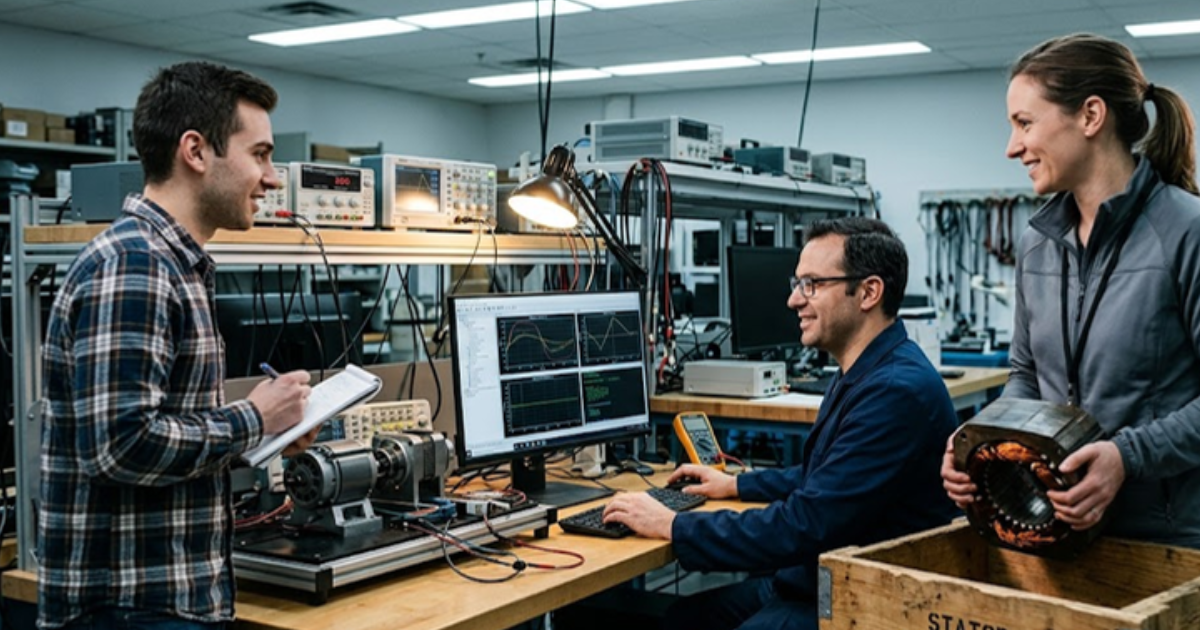
Match the model to the question rather than to the budget. Early control work needs speed and iteration. Switching-level behaviour needs FPGA solving. Power integrity and thermal response need current actually flowing. Choosing one fidelity level for an entire project guarantees you’ll overpay somewhere and under-test somewhere else.
- Offline machine models for early control structure work and regulator gain selection
- Signal-level hardware in the loop once controller hardware and production software exist
- FPGA machine models when switching frequency and current ripple change the answer
- Power-level emulation when the inverter under test has to push genuine current
- Dynamometer cells for efficiency mapping, mechanical correlation and formal sign-off
That ladder isn’t strictly sequential. Plenty of projects run offline models and power-level emulation in the same week, since the two answer separate questions. What matters is that each rung has an owner and an exit criterion. A model nobody has correlated against measured data is an opinion, and opinions get ignored the moment schedule pressure arrives.
“A model nobody has correlated against measured data is an opinion, and opinions get ignored the moment schedule pressure arrives.”
Common failure modes that undermine motor simulation projects
Most motor simulation efforts fail for process reasons rather than technical ones. Parameters go stale, models live on one engineer’s laptop, and nobody owns the correlation between bench results and cell results. The physics is usually fine. The bookkeeping around it isn’t.
One pattern shows up after almost every machine redesign. The magnet grade shifts, the flux tables don’t, and three months of control tuning happens against a motor that no longer exists. The error surfaces on the dynamometer as a torque offset nobody can explain. Interface modelling causes much of the remaining trouble, because resolver excitation, current sensor bandwidth and PWM synchronization all shape what the controller actually measures. Version the parameter set alongside the control software, tag every result with its model revision, and re-correlate after any machine change.
Building a drive validation practice your team will trust
Trust in motor simulation comes from correlation evidence and steady practice rather than from headline fidelity claims. Pick a small set of anchor operating points, measure them in the cell, match them on the emulator, and repeat that check every time the machine or the model changes.
Teams that get real value out of this are unremarkable about it. They keep a short correlation report anyone can read, they retire models that no longer match hardware, and they’re honest about the operating regions where the model is weakest. Power-level emulation on an OPAL-RT OP1630 bench sits inside that discipline rather than replacing it, giving the inverter under test genuine current to push while the machine behaviour stays under software control.
None of this is exotic. It’s the same discipline good test engineering has always asked for, applied to a machine made of equations. Get the parameters right, correlate honestly, and your drive team spends its scarce cell hours on the questions that genuinely need iron and copper.

Power Electronics
09 / 30 / 2026
FPGA simulation for power electronics and motor drives
A technical comparison of CPU and FPGA solver architectures for power electronics and motor drive simulation, covering the timestep each reaches and how to split a model between them.
Power Electronics
09 / 29 / 2026
How to model and control a T-type three level inverter
An engineering overview of the T-type three level inverter leg, covering how it reaches three voltage levels, where device stress lands, and how neutral point balancing and modulation shape control.
Simulation
09 / 28 / 2026
How CHIL signal-level testing validates embedded controllers
A practical look at signal level controller hardware in the loop testing, covering I/O ranges, sensor emulation, latency and the setup checks that make embedded controller results trustworthy.