Key Takeaways
- A DC fast charger is only proven when it has met the full range of vehicle and grid conditions, and emulation at power is the practical way to supply that range.
- Bench testing should remove design defects first, so field trials are reserved for what only an installed site reveals.
- A maintained library of vehicle and grid cases turns every firmware release and field failure into a repeatable regression run.
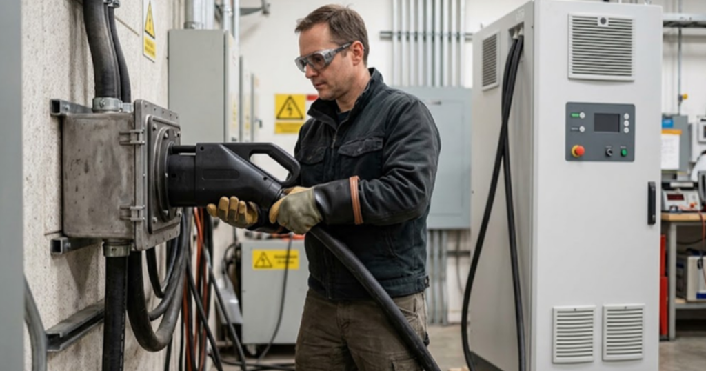
EV charging station testing with power hardware in the loop lets you prove a DC fast charger against every vehicle and grid condition it will meet before a single unit ships to site.
High-power charging is growing faster than any lab can keep up with physically. The global stock of ultra-fast chargers rated at 150 kW or above grew by over 50% in 2024, and each of those units has to work with battery packs its designers have never seen. You’ll only ever test the vehicles you can borrow, on the supply your building happens to have.
A power-level test bench solves the coverage problem at its source. An emulated vehicle and an emulated grid sit on either side of the real charger, both exchanging real power, both controlled by models you can adjust in seconds. The strongest charger programs treat emulation as the main test asset. Physical vehicles and field trials then confirm what the bench has already shown.
What power hardware in the loop means for a fast charger
Power hardware in the loop (PHIL) connects a real charger to simulated surroundings through power amplifiers. A real-time simulator solves models of the grid and the vehicle battery, the amplifiers reproduce those voltages and currents at the charger’s terminals, and measurements feed back into the models. The charger carries real power throughout.
Picture a 150 kW charging cabinet on the bench. Its AC input connects to an amplifier acting as the utility supply, and its DC output connects to a second amplifier acting as a battery pack. When the charger ramps current, the simulated pack voltage rises as a real pack’s would, and the simulated grid voltage dips according to the modelled line impedance.
This matters because controller-only testing stops at signals. Signal-level hardware in the loop checks firmware logic, yet it can’t show you how the power stage, filters, contactors and protection circuits respond under load. You’re testing the product a driver will plug into.
Why physical vehicles leave gaps in charger test coverage
Physical vehicle testing covers only the cars, states of charge and temperatures you can arrange on a given day. Every vehicle model brings its own pack voltage, current limits and communication timing, and no lab holds them all.
“Coverage ends up defined by logistics instead of engineering risk.”
Consider what one session with a borrowed car gives you. The pack arrives at 40% state of charge, at a mild temperature, and the session completes. You’ve learned that one combination works. You haven’t seen the same car at 5% on a cold morning, when its pack limits current hard, or near full, when it asks for a long taper at high voltage.
Fault cases are worse. Nobody will let you weld a contactor or break an isolation barrier inside their prototype vehicle, so those cases wait until a driver finds them. Drivers do find them, since 14% of EV owners in a 2025 United States study reported visiting a public charger without successfully charging.
How an emulated vehicle exercises the charger’s DC output
An emulated vehicle is a battery model running in real time, paired with a DC amplifier that absorbs the charger’s output and a communication interface that speaks the charging protocol. It presents the charger with any pack voltage, state of charge and current limit you define.
Voltage class is the obvious case. As a generic illustration, a 150 kW session into an 800 V pack needs about 188 A, while the same power into a 400 V pack needs about 375 A. The charger’s power modules, cable rating and control loops behave very differently at those two operating points. An emulated pack lets you sweep between them in minutes.
Communication deserves equal attention. A charging session is a negotiated sequence covering the handshake, cable check, pre-charge, current delivery and shutdown, and each vehicle times those steps differently. An emulated vehicle will stretch a response to the edge of the allowed timeout, send a current request that jumps abruptly, or drop the link mid-session. You’ll see how the charger’s state machine copes.
Fault injection is where emulation pays for itself. The model opens a simulated contactor under load, reports an isolation fault or goes silent, and the only thing at risk is a test script.
“Fault injection is where emulation pays for itself.”
What an emulated grid reveals about the charger’s AC front end
An emulated grid is a network model driving an AC amplifier at the charger’s input. It reproduces the voltage, frequency, impedance and distortion of any connection point, which shows how the charger’s rectifier stage and its controls behave on supplies far weaker or noisier than the one feeding your lab.
Take a highway site at the end of a long rural feeder. Several chargers ramp at once, the voltage at the connection point sags, and each charger’s front end has to hold its DC link steady while staying inside its harmonic and power factor limits. On the bench you set the feeder impedance in the model, start the ramp and watch the interaction.
Disturbances follow the same logic. A voltage sag to 80% of nominal for a few hundred milliseconds, a frequency excursion or a phase imbalance can each be scripted and replayed against every firmware build. Utilities won’t supply those events on request, which is why so many chargers meet them for the first time in service.
Which test cases belong on the bench before site commissioning
The cases that belong on the bench are the ones a site can’t supply safely or repeatably. That covers the extremes of pack voltage and state of charge, communication edge timing, grid disturbances and every protective shutdown. A useful starting set has 5 groups.
- Full charge sessions across the complete output voltage range at low, middle and high state of charge.
- Protocol timing tests that hold each handshake, cable check and pre-charge step at its limits.
- Current request steps and tapers that stress the output control loop.
- Grid sags, swells, frequency shifts and weak feeder conditions at rated power.
- Protective responses to contactor, isolation, overtemperature and communication loss faults.
Run the protection cases early and at reduced power, so the bench itself is proven safe before you push to rated output. Automate everything that passes, since a regression suite that runs overnight on each firmware release is the lasting return on the bench.
How bench results compare with field trials for charger validation

The main difference between bench testing and field trials is control. A PHIL bench lets you choose the vehicle and grid condition, repeat it exactly and measure everything, while a field trial shows you the installed site as it is, including the cable runs, weather and driver behaviour that no model fully captures.
| What you need to know | What the PHIL bench gives you | What a field trial gives you |
| How many vehicle types are covered | Any pack you can model is available the same afternoon. | Coverage stops at the vehicles you can borrow. |
| How repeatable each result is | Each case replays identically on every firmware build. | Conditions shift with weather and grid loading. |
| How faults are handled | Faults are scripted with no vehicle at risk. | Faults can’t be staged safely. |
| Which grid conditions are seen | Weak feeders and disturbances are set in the model. | Only the local supply is observed. |
| How installation effects are captured | Site wiring is approximated. | The installation is tested as built. |
The comparison points to a sequence. Bench work removes the design defects, so field trials can focus on what only a site reveals. That’s the pattern across the PHIL programs we support at OPAL-RT. The OP1430 PHIL Prime bench emulates both the vehicle and the grid at power, so a charging station’s controls meet conditions a conventional bench can’t recreate.
Where a disciplined charger test program pays off over time
A disciplined charger test program pays off every time the product changes. Firmware updates, new vehicle models and new site types keep arriving for years after launch, and a bench with a maintained library of vehicle and grid cases turns each of those into an overnight regression run.
The teams that get this right treat every field failure as a missing test case, rebuild it on the bench and keep it in the suite for good. Over a few release cycles the library becomes a record of everything the charger has ever struggled with, and it’s what stops an old problem from returning quietly.
Drivers never see any of this work. They see a charger that starts on the first try with a car it was never physically tested against, on a feeder nobody at the factory has visited. That outcome comes from engineers who refused to let vehicle availability decide what got tested. It’s the same conviction behind the PHIL benches we build at OPAL-RT, where the vehicle and the grid arrive at your terminals so the hard cases happen in your lab first.
Power Electronics
10 / 15 / 2026
Flying capacitor converter simulation for multilevel designs
How a flying capacitor converter balances its capacitor voltages through switching, where that balance breaks, and what a switching-accurate simulation has to capture.

Industry applications
10 / 12 / 2026
Validating eVTOL electric propulsion before the first flight article
A walk through motor, inverter and battery validation for eVTOL aircraft and the points where real-time simulation carries propulsion evidence ahead of flight test.
Power Electronics
10 / 11 / 2026
Totem pole PFC design and real time validation
How a totem pole PFC works, why its control is hardest at the AC zero crossing, and how real-time testing checks that transition before hardware is built.