Grid forming vs grid following inverters and why the difference matters for protection engineers
Microgrid
05 / 20 / 2026

Key Takeaways
- Grid forming control must be treated as source behaviour, because it sets the waveform that protection schemes measure during faults and islanded operation.
- Relay coordination depends on converter current limits, control mode logic, and post-fault voltage recovery rather than on synchronous machine assumptions.
- Closed loop testing is the safest way to validate weak-grid performance, mode transfer, and hybrid source behaviour before field settings are finalized.
Protection engineers need to model grid forming behaviour as a source, or relay settings will misread faults, frequency events, and islanded operation.
Wind and solar supplied 13.4% of global electricity in 2023, which means more feeders and plants now depend on inverter controls for voltage and frequency support. That shift turns inverter control from a planning detail into a protection issue. You can’t coordinate relays correctly if you assume every source behaves like a synchronous machine. You also can’t judge frequency support from nameplate data alone.
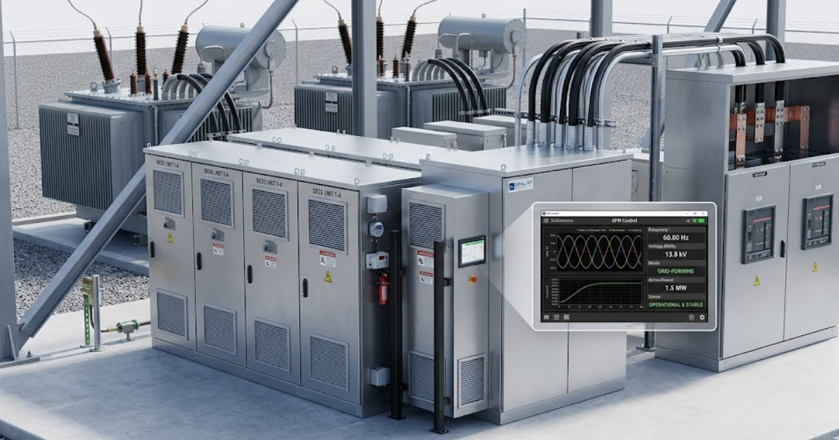
A grid forming inverter sets local voltage frequency reference

A grid forming inverter establishes voltage magnitude, phase angle, and frequency at its terminals. It behaves like a controllable source rather than a device that waits for the grid to tell it what to do. That local reference lets other devices synchronize to it. Protection engineers should treat that behaviour as part of the system source model.
Consider a battery plant that black starts a remote microgrid. Its control sets 60 Hz and terminal voltage before any motor load connects, then it holds that reference as pumps and conveyors come online. Relay pickup, underfrequency timing, and bus undervoltage performance all depend on that source behaviour. You’re no longer studying a passive current injector. You’re studying a source that can support a bus through a disturbance and shape what the relay measures during the first moments of a fault or load step.
“Protection settings fail when source behaviour is assumed instead of modelled.”
Grid following control needs an external voltage reference
The main difference between grid following and grid forming control is simple. Grid following locks onto a grid that already exists. Grid forming creates the waveform that other devices can follow. Protection studies change because loss of reference affects these two controls in completely different ways.
On a stiff feeder, a solar plant can use grid following control with little trouble because the transmission system supplies a strong angle reference. The same control on an islanded microgrid will stall or trip once that reference disappears. That is why a microgrid with storage often uses one grid forming unit and several grid following units. The first unit anchors the bus. The others inject power around that anchor.
| What you should assess | How grid forming and grid following control differ in practice |
| Voltage and frequency are set locally by grid forming control. | Grid following control locks to an external waveform and needs that waveform to remain healthy. |
| Loss of the bulk grid can still leave a grid forming source holding up an islanded bus. | Loss of the bulk grid often removes the reference that a grid following source needs to stay synchronized. |
| Fault response is shaped by a voltage source controller with current limits and angle logic. | Fault response is shaped by current injection logic that usually tracks a phase locked estimate of the grid. |
| Frequency support comes from droop and virtual inertia settings that the controller actively applies. | Frequency support is usually secondary and depends on a pre-existing grid signal to measure deviation. |
| Relay studies must model source stiffness, mode transfer, and post-fault voltage recovery. | Relay studies must check what happens when the external reference weakens, shifts, or disappears. |
Protection settings fail when source behaviour is assumed
Protection settings fail when source behaviour is assumed instead of modelled. Relays see current magnitude, current angle, and voltage recovery, and all three can shift when the source is converter controlled. A setting file copied from a synchronous machine study will miss those shifts. That mistake becomes visible during faults, feeder energization, and islanding events.
Consider a feeder with battery storage. Phase overcurrent elements might expect a strong current surge and a familiar decay shape, yet the inverter current stays limited and controlled while voltage recovery is much faster than expected after fault clearance. Ground elements can also see unusual sequence content because converter controls and filters shape the waveform. That mistake usually appears after interconnection studies copy old short circuit assumptions into relay files. Protection still looks correct on paper, but the relay is responding to a source model that never existed at the point of connection.
Fault current from grid forming inverters stays limited during faults
Fault current from grid forming inverters stays limited because semiconductor devices and control loops impose hard current ceilings. The inverter will regulate current, voltage, or both according to its fault strategy. That means protection cannot count on the high current margin common with synchronous machines. Relay sensitivity and timing must reflect that limit.
Picture a close-in three-phase fault on a collector feeder. The inverter can hold output near a modest margin above rated current while it prioritizes terminal voltage support or current direction control, so an overcurrent relay sees much less separation between load and fault than you’d expect from a rotating source. Distance elements can also misread apparent impedance if the source angle stays tightly controlled during the event. Voltage depression can be uneven across phases, which complicates negative-sequence elements. You won’t solve that with lower pickup alone. You need a source model that matches current limit, control priority, and recovery sequence.
Frequency support comes from droop settings plus virtual inertia
Grid forming inverters support frequency with active power control, droop response, and virtual inertia functions. Synthetic inertia comes from measured frequency or rate of change signals that command a brief power change from stored energy or curtailed headroom. That response is fast and programmable. It still depends on control tuning, energy margin, and plant operating limits.
Take an islanded microgrid facing a sudden motor start. Frequency begins to fall, the controller senses that movement, and the inverter injects extra active power according to its droop and inertia settings while holding voltage reference for the rest of the bus. Good performance keeps the frequency nadir above load shedding thresholds. Poor tuning causes overshoot, hunting, or delayed recovery. Protection engineers need the actual control settings because underfrequency relays are responding to a shaped control response, not to the physical inertia of a turbine shaft.
Relay coordination must match converter limits across control modes
Relay coordination must reflect the converter’s operating mode because source behaviour changes when the control mode changes. Current ceiling, sequence current support, and voltage recovery can all differ between grid following and grid forming operation. A relay set from only one mode won’t stay well coordinated after a mode transfer. You should study the same mode logic that the plant controller will use.
After an islanding command or breaker event, a battery inverter can export one fault response in grid following mode and another in grid forming mode. Feeder protection, bus protection, and transfer trip logic all need those mode changes represented in the study set. Focus first on these checks.
- Verify the current ceiling and how long it is sustained.
- Check the exact logic that switches between control modes.
- Confirm negative-sequence support during unbalanced faults.
- Review ride-through logic against relay trip timing.
- Test grid-connected cases separately from islanded cases.
Hardware in the loop testing reveals weak grid control risks
Hardware in the loop testing exposes control problems that steady-state studies miss. It lets you run the actual controller against a simulated weak grid, staged faults, breaker actions, and islanding events. That closed loop setup shows how the inverter and protection interact in time. You can see unstable mode transfer, poor fault recovery, and PLL loss before site commissioning.
Grid-scale battery additions reached 42 GW in 2023, so these tests now sit in routine utility work rather than a narrow pilot class. A weak-grid energization test run on an OPAL-RT platform can stage a fault, a reclose, and an islanding sequence against the actual plant controller while relays and breaker logic stay in the loop. That setup exposes current saturation, unstable voltage recovery, or bad sequencing between plant controls and protection. You don’t get that confidence from short circuit software alone. You get it from watching the controller react to the exact disturbances the relay will face.
“Good protection starts with an honest source model and disciplined validation of how each device behaves during stress.”
Synchronous condensers still cover duties grid forming inverters cannot
Grid forming inverters do not replace synchronous condensers in every case. A synchronous condenser still supplies physical inertia, strong fault current, and short-term overload that converters usually cannot match. Grid forming control covers voltage and frequency support with great precision, yet it does not erase every system strength problem. Protection engineers should expect hybrid source designs on weak nodes.
Consider a wind and storage plant connected to a weak transmission bus. The inverter can anchor voltage and frequency for plant control, while the condenser raises fault level and improves source stiffness for protection and fault recovery. That mixed source picture is what your relay sees, so that is the picture your study must reflect. Teams using OPAL-RT often test the hybrid case for exactly that reason. Good protection starts with an honest source model and disciplined validation of how each device behaves during stress.
Real-time solutions across every sector
Explore how OPAL-RT is transforming the world’s most advanced sectors.

Industry applications
06 / 29 / 2026
What IEEE 2030.5 means for DER communication and dispatch interoperability
A practical guide to IEEE 2030.5, DERMS communication flow, protocol choice, device scope, testing, and tariff-led utility adoption.

Simulation
06 / 28 / 2026
How defense labs scale validation with real-time simulation platforms
This guide explains how defence labs use real-time simulation, HIL testing, and reusable models to validate vehicles and robotics before field trials.

Simulation
06 / 27 / 2026
Wind turbine simulation and testing for grid compliance engineers
This piece explains how engineers use wind turbine simulation, EMT studies, hardware-in-the-loop testing, and traceable metrics to support grid compliance work.