IEC 61850 GOOSE messaging and how to test it for substation automation projects
Power Systems
05 / 19 / 2026

Key Takeaways
- IEC 61850 GOOSE testing starts with SCL files, datasets, and signal meaning before live packet work.
- Low millisecond timing only holds when multicast design, switch handling, and subscriber logic are tested as one chain.
- DNP3 still has a valid role for supervisory exchange, but trip logic belongs on GOOSE.
Reliable IEC 61850 GOOSE testing starts with engineering discipline long before you capture a single packet.
IEC 61850 testing matters because protection traffic only helps when the message meaning, timing, and subscriber response all match the protection intent. Power outages cost the U.S. economy between $28 billion and $169 billion each year, which is a useful reminder that weak protection communication carries a much larger system cost. You’re not validating a network in isolation. You’re proving that the substation will trip, block, or interlock exactly when it should.
IEC 61850 GOOSE moves protection signals without polling delays
IEC 61850 GOOSE sends status changes and trips as event messages, so protection devices react as soon as a state changes instead of waiting for a poll cycle. That behaviour makes GOOSE a strong fit for interlocking, blocking, transfer tripping, and breaker failure logic inside the substation.
A feeder relay that detects an internal fault can publish a trip state immediately, and a breaker control IED can subscribe to that state without asking for an update first. The message is multicast, so several devices can react at the same time. That matters when a bus differential trip must reach multiple bays at once. You’re testing speed, but you’re also testing shared intent across several subscribers.
GOOSE works because the message repeats in a tight sequence after a state change, then slows its repetition rate after the new state is stable. That repetition helps subscribers keep a valid state even if one frame is lost. Protection engineers sometimes focus only on the packet trace, yet the bigger check is simpler. Every bit in the dataset has to represent a clear action that another device will interpret the same way.
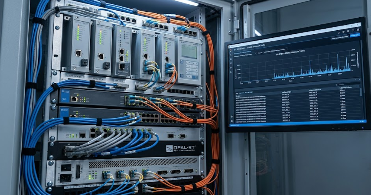
GOOSE speed depends on multicast design across the station bus
GOOSE performance depends on switch behaviour, multicast forwarding, priority tagging, and network segmentation across the station bus. Latency problems usually come from poor traffic handling rather than the protocol itself. A clean design keeps protection traffic predictable during faults, maintenance traffic, and device restarts.
One common failure starts when a managed switch is left with broad multicast flooding across ports that don’t need GOOSE traffic. A protection bay then receives extra frames from unrelated publishers, and the subscriber still works until a burst of engineering traffic arrives. Your packet capture will show GOOSE frames, yet the transfer time will drift. That is why VLAN design and priority settings deserve the same attention as relay logic.
Station bus testing should include normal loading and stressed conditions. A breaker operation during a maintenance laptop file transfer is a useful check because it exposes queue handling inside the switch fabric. You won’t get a meaningful IEC 61850 result from a flat network that hides port congestion. Good network design keeps GOOSE traffic short, local, and prioritized.
“IEC 61850 GOOSE sends status changes and trips as event messages, so protection devices react as soon as a state changes instead of waiting for a poll cycle.”
Start IEC 61850 testing with SCL file validation
SCL validation is the first serious test because it confirms that the engineering model matches the devices you plan to commission. If the ICD, CID, SSD, or SCD files are inconsistent, packet tests will only tell you that the wrong design was implemented correctly.
- Check that every publisher and subscriber uses the same logical node references.
- Confirm that dataset members match the signal names approved in protection logic.
- Verify the control block settings, especially MAC address, VLAN, and priority fields.
- Review revision numbers so subscribers won’t reject an updated dataset silently.
- Make sure the imported file maps each signal to the intended physical I/O or internal point.
A transfer-trip scheme shows why this step matters. The logic can look perfect in the relay setting file, yet the SCD file might map the breaker failure initiate bit to the wrong data object. Everything will compile, and the substation will still behave incorrectly. You’ll save days of troubleshooting when the engineering file is treated as a test object rather than clerical output.
Verify datasets match each protection function before signal tests
Dataset verification comes before signal injection because each protection function depends on the exact data object, quality state, and control block revision it expects. A subscriber can receive a valid GOOSE frame and still act on the wrong meaning if the dataset structure is wrong.
A breaker failure scheme makes this clear. The publisher might send breaker position, protection operate, and lockout status in one dataset, but the subscriber may only need two of those points and may expect them in a different order or with a different functional constraint. A live network capture won’t always flag that mismatch. You need to compare the intended protection function to the dataset content point by point.
Signal tests become useful only after that mapping is trusted. Inject a fault, force a breaker auxiliary contact, or toggle an interlock, then confirm that the correct dataset member changes and the subscriber logic reacts. You’re verifying semantics as much as transport. That is the step that separates IEC 61850 testing from a basic Ethernet health check.
“You’re measuring end-to-end protection performance, not just frame transit.”
Protection schemes need GOOSE latency in low milliseconds
Protection GOOSE traffic must arrive within low millisecond limits because trip and block logic lose value when communication delay approaches the clearing time of the faulted element. The practical target for high-speed protection traffic is commonly less than 4 ms for Type 1A performance.
A lab test that shows 1.5 ms average delay during idle traffic doesn’t finish the job. You also need measurements during burst events, device restart, and switch reconvergence. A subscriber that responds in 2 ms most of the time but slips to 9 ms during a network storm will still break a permissive overreach or bus trip scheme. Latency testing only matters when it includes the bad moments.
Time stamps, sequence numbers, and retransmission intervals help you separate transport delay from application behaviour. Watch the state change, the first retransmission, and the subscriber output change as one event chain. If the relay waits on internal logic after receiving the frame, the packet trace alone won’t tell the full story. You’re measuring end-to-end protection performance, not just frame transit.
Interoperability issues usually start with vendor engineering defaults
Interoperability failures usually come from default engineering choices such as dataset order, quality handling, revision control, and VLAN settings. Devices from different vendors can support IEC 61850 well and still miss each other when defaults are left untouched. You should expect cross-vendor testing to expose assumptions that same-vendor projects hide.
A common case appears after a relay replacement. The new device publishes the same logical signal names, yet its default control block uses a different revision number and a different retransmission pattern. The subscriber sees traffic and still rejects the update or holds an older state. That kind of fault is hard to spot unless your test plan includes deliberate cross-vendor publish and subscribe checks.
Interoperability testing should move from engineering import to live behaviour without skipping the middle. Validate the file import, confirm the control block values, trigger the signal, and watch the output contact or internal logic point. That sequence will expose where the mismatch starts. Generic conformance claims won’t tell you if your exact scheme works on your exact station bus.
IEC 61850 tools must capture packets replay events
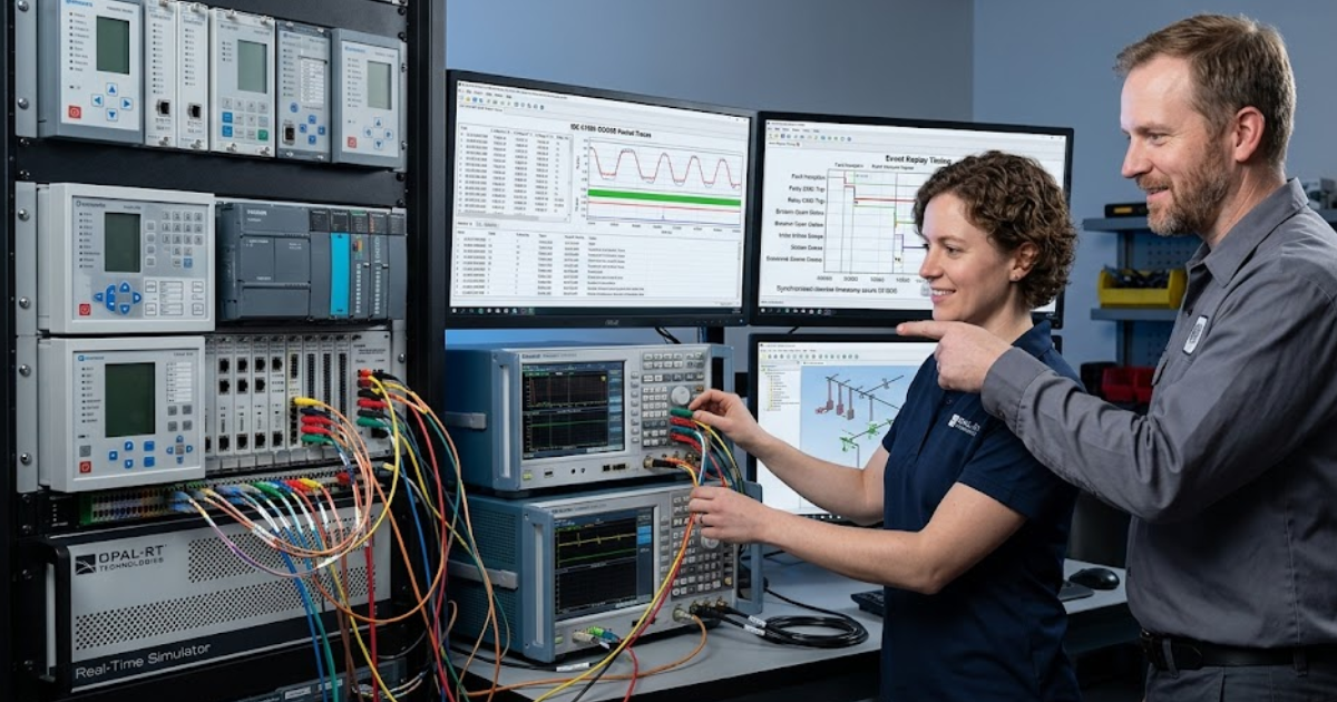
Useful IEC 61850 testing needs a tool set that captures frames, injects events, measures timing, and observes subscriber outputs at the same time. No single tool proves the whole scheme. You’re building a chain of evidence from engineering files to live device response.
A closed-loop setup can make that chain much clearer. A real-time simulator from OPAL-RT can apply a fault, publish or subscribe GOOSE traffic, and show how the protection logic reacts under controlled timing pressure. Packet capture still matters, yet it becomes far more useful when paired with a known disturbance and a measured relay output. That is how you test the scheme rather than only the network.
| Tool focus | What it proves during testing |
| SCL validation software | It confirms that the engineered model, signal names, and control blocks match the intended substation design. |
| Packet capture and analysis | It shows frame timing, retransmission behaviour, multicast addressing, and priority markings on the live network. |
| Network traffic generation | It reveals how switches handle congestion and whether GOOSE timing stays stable during heavier background traffic. |
| IED test sets | They inject status changes and verify that subscribed relays change logic state or output contacts correctly. |
| Time-synchronised disturbance playback | It links fault conditions, GOOSE messages, and relay actions into one measurable event sequence. |
DNP3 still serves slower supervisory traffic outside trip logic
The main difference between IEC 61850 GOOSE and DNP3 is that GOOSE carries event traffic for time-sensitive protection logic, while DNP3 handles supervisory data that can tolerate slower delivery. You should keep trip paths on GOOSE and reserve DNP3 for polling, control, alarms, and control centre exchange.
A substation gateway that reports breaker status and analog values to a control room is a good DNP3 use case. A breaker failure initiate, bus trip, or transfer-trip permissive is not. Those signals need deterministic multicast behaviour inside the station bus, and DNP3 was never built for that job. Mixing the roles usually creates long troubleshooting cycles because the protocol choice itself is wrong.
Teams that test both protocols in the same project usually reach the same judgement. Clear signal ownership, disciplined SCL control, and end-to-end timing checks matter more than protocol slogans. OPAL-RT fits that execution stage when you need to exercise protection logic under repeatable fault conditions, but the same lesson holds on any serious test bench. Careful engineering will keep IEC 61850 GOOSE trustworthy, and DNP3 will keep serving the slower supervisory layer where it belongs.
Real-time solutions across every sector
Explore how OPAL-RT is transforming the world’s most advanced sectors.

Microgrid
05 / 20 / 2026
Grid forming vs grid following inverters and why the difference matters for protection engineers
This guide explains how grid forming and grid following inverters differ in source behaviour, fault response, frequency support, testing, and relay coordination.

Microgrid, Energy
05 / 18 / 2026
Battery energy storage system testing that grid operators trust
This piece explains how utilities validate a battery energy storage system through acceptance criteria, closed-loop testing, commissioning, protection checks, duration tests, and traceable evidence.

Simulation
05 / 15 / 2026
Cyber-physical systems simulation for critical infrastructure validation
A guide to validating cyber-physical systems for critical infrastructure through closed-loop simulation, sensor modelling, embedded systems testing, and power grid protection studies.