How to validate protective relay settings with real-time simulation before commissioning
Simulation
05 / 04 / 2026

Key Takeaways
- Closed loop simulation is the strongest method for proving protective relay settings because it tests timing, logic, and I/O behaviour under dynamic fault conditions.
- Static secondary injection remains useful for setup checks, but it won’t verify full scheme performance under source shifts, breaker status changes, and stressed coordination cases.
- Lab acceptance has the most value when it uses the same pass or fail criteria, evidence package, and timing targets expected during commissioning.
Closed-loop real-time simulation is the most reliable way to prove protective relay settings before a substation is energized.
That stance matters because commissioning errors do not stay in the lab. A single bad trip path can remove a healthy line, block a needed trip, or stretch an outage window that crews already struggle to protect. U.S. electricity customers experienced a little more than 5.5 hours of power interruptions in 2022, which shows how little room utilities have for avoidable protection mistakes. Protective relay testing before site energization gives you a safer place to prove settings, logic, timing, and I/O behaviour under conditions that a bench test can’t reproduce.
“A relay that trips at the right current in a static test can still fail when voltage collapses, current saturates, or breaker status changes at the wrong instant.”
Real-time simulation verifies relay settings before field commissioning
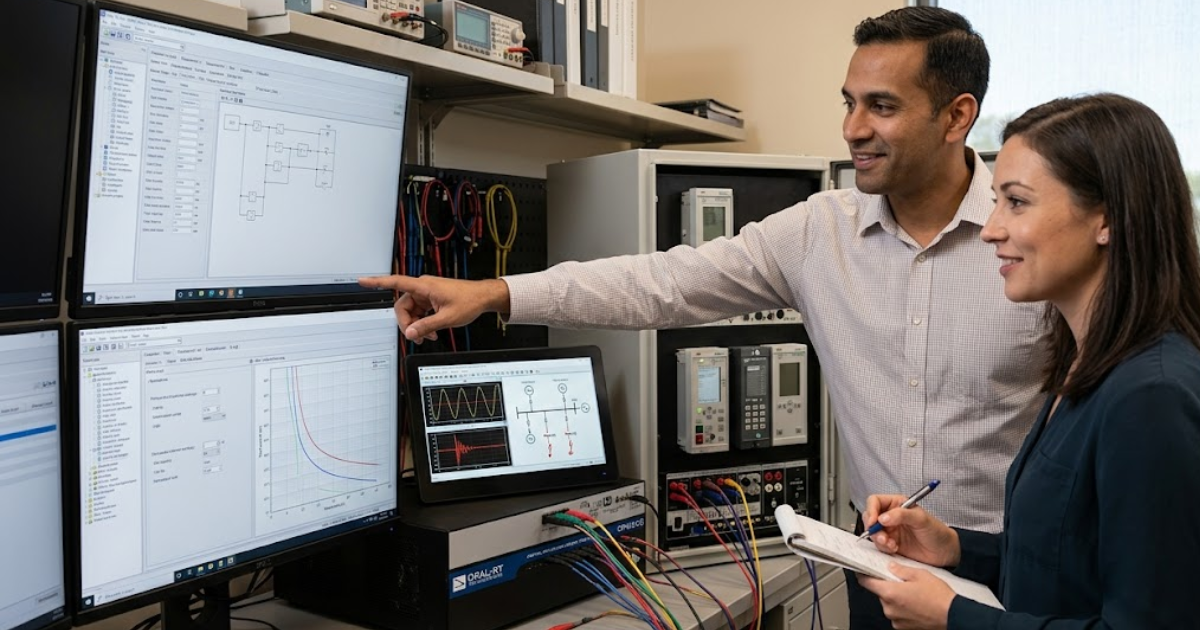
Real-time simulation verifies relay settings by forcing the relay to respond to a moving power system rather than a scripted stream of isolated test values. You see pickup, timing, supervision, output logic, and reset behaviour in one continuous test. That makes relay testing much closer to commissioning conditions and far better for setting verification.
A line relay gives a clear example. Zone timing can look correct during simple secondary injection, yet the same relay can delay or overreach when source strength shifts during a close-in fault, breaker failure logic starts, and autoreclose timers interact with live inputs. A closed-loop test exposes that chain because the relay’s output changes the simulated network and the network then feeds back into the relay.
You also get evidence that matters to engineers signing off settings. Oscillography, event records, trip contact timing, and simulated fault states line up in one repeatable run. That means you’re not guessing which value caused a trip. You’re proving that the protection relay will act correctly when voltages sag, currents swing, and binary inputs arrive a few milliseconds apart.
Static secondary injection misses failures that closed-loop tests catch
Static secondary injection is useful for point checks, but it won’t expose every failure mode that causes trouble after energization. It proves individual elements and wiring paths under fixed conditions. It does not prove how the full protection relay behaves during a live disturbance with feedback from breaker status and changing system quantities.
A relay that trips at the right current in a static test can still fail when voltage collapses, current saturates, or breaker status changes at the wrong instant. Distance elements are a common case. The measured impedance can shift during a fault because the polarizing quantity decays, a remote source feeds the fault, or a weak infeed changes the voltage profile. Static relay testing won’t show that sequence well.
You still need secondary injection for contact checks, analogue scaling, and basic logic confirmation. The problem starts when teams treat it as full validation. Protective relay testing needs both methods, with static checks used for setup and closed-loop testing used for proof. That sequence cuts false confidence, which is one of the costliest problems in protection work.
A credible test starts with the right network model
A credible relay setting verification effort starts with a network model that matches the protection study assumptions and the relay application details. If source impedance, line data, transformer taps, instrument transformer ratios, or breaker logic are wrong, your lab result will be wrong as well. Model quality belongs inside relay testing and needs to be treated as part of the validation scope.
A 230 kV line project shows why this matters. If the test model omits remote infeed, your distance relay can look secure in the lab and overreach after energization. If the model uses ideal voltage sources instead of the actual source short circuit levels, time delayed elements and load encroachment supervision can behave very differently from site conditions. Good protection relay validation starts with study files, relay settings files, and as built I/O mapping checked against each other.
Labs often use OPAL-RT to run that model in closed loop with live analogue and binary I/O so engineers can test the relay against multiple source conditions without rebuilding the bench each time. That setup helps you compare study intent with relay response and close gaps before they reach the field. A fast simulator is helpful, but disciplined model review is what makes the results credible.
Distance relay validation depends on fault placement fidelity
Distance relay validation in the lab depends on where the fault is placed, how it is modelled, and what the relay sees during the first cycles. Fault location accuracy matters because zone reach, directional supervision, and permissive logic all respond to apparent impedance instead of simple fault labels. Good testing reproduces the electrical view seen by the relay.
A useful test set for Zone 1 starts with close in, midline, and near remote bus faults on each loop. Then you add arc resistance, remote infeed, and load current before the fault. A phase to ground fault at 80% of the line with 20 ohms of fault resistance can tell you much more than a clean bolted fault at 50%. The relay may still trip, but the measured impedance path and timer behaviour will show if the reach is set too aggressively.
You also need off-nominal cases. Power swings, series compensated lines, and voltage inversion during weak source faults can confuse a setting that looked fine in a simple study. The lab is where you verify that distance protection remains selective under those conditions. If the fault placement is too coarse, the relay can appear secure while the dangerous edge cases go untested.
Coordination testing should prove timing margins under stressed faults
Protection coordination testing should prove timing margins under the fault conditions that put your grading most at risk. Basic time current checks are only the start. You need to show that primary and backup elements keep their intended separation when current levels, source contribution, and breaker clearing times shift during a disturbance.
Settings and logic errors remain a large share of misoperations. NERC has reported that settings, logic, and design issues account for more than 50% of protection system misoperations in recent annual reviews. That is why coordination testing can’t stop at nominal cases. You need cases that squeeze the time margin.
Consider a feeder overcurrent relay backed up by a transformer relay and an upstream bus relay. Minimum source faults can expose underreaching elements, while maximum source faults can compress operating margins enough to create overlap. Breaker failure initiation adds another layer because an intended 250 ms margin can disappear if breaker status input is delayed or mapped incorrectly.
| Validation focus | What the evidence should show |
| Primary element reach | The intended element operates only for faults inside its protected zone under low and high source conditions. |
| Backup timing | The backup relay keeps a clear time margin after the primary relay and breaker clear the fault. |
| Supervision logic | Voltage, direction, breaker status, and permissive inputs support the trip path only when the scheme requires them. |
| Reset behaviour | The relay resets cleanly after cleared faults and does not leave timers or latches in the wrong state. |
| Event evidence | Oscillography, event logs, and output timestamps tell the same story without gaps or unexplained delays. |
Most post-commissioning misoperations start at relay interfaces
Most post-commissioning misoperations start at interfaces because relay logic only sees the signals you wire and map into it. A sound setting file can still misoperate when CT polarity is reversed, a binary input is inverted, a trip matrix is mislabelled, or the breaker status point arrives late. Interface validation is part of protective relay testing.
A feeder relay can illustrate the problem. The settings may be perfect, yet breaker failure logic will start on every external fault if the 52a status is wired backwards. A transformer differential scheme can restrain correctly in the study and still trip in the field if one CT secondary is landed on the wrong phase or the analogue channel scaling is off. Those failures usually look like setting mistakes until you trace the interface path.
- Confirm CT and VT ratios against the relay analogue channel mapping.
- Verify polarity on every phase current and voltage input.
- Test each binary input with the final logic equations loaded.
- Measure trip output timing through the actual I/O path.
- Match event records to wiring drawings and breaker status changes.
That list is simple, but it catches a large share of site surprises. You’re checking the relay as installed against the wiring and logic that will exist on site. Closed-loop testing makes these issues visible because the relay sees dynamic quantities while the I/O path is exercised at the same time.
Lab testing can remove most outage work
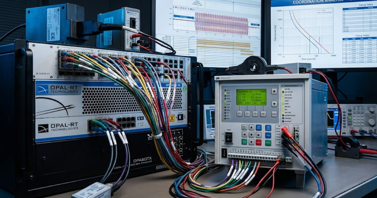
Lab testing can remove most outage work because setting verification, dynamic logic testing, and coordination proof do not require an energized yard. You still need site checks for final wiring, instrument transformer circuits, and plant integration. The heavy analytical work belongs in the lab, where repetition is safe and fault cases are easy to rerun.
A practical commissioning plan shifts nearly all relay testing ahead of the outage window. Engineers load the final settings, connect the relay to the simulator, run a structured test set, and record pass or fail evidence before the relay ever reaches the panel. Site time then focuses on point-to-point checks, polarity confirmation, primary injection where needed, and final end-to-end checks with the actual plant interfaces.
That approach reduces schedule risk as well as technical risk. If a distance element needs a reach correction or a binary input needs inversion, you can fix it in hours instead of holding crews and switching authorities on site. Field commissioning should confirm wiring and plant integration, while the lab should carry the heavier burden of proving settings and logic.
“Field commissioning should confirm wiring and plant integration, while the lab should carry the heavier burden of proving settings and logic.”
Lab acceptance should mirror commissioning pass fail criteria
Lab acceptance should mirror commissioning pass or fail criteria so the evidence you collect before energization has direct value at site. The same fault cases, timing limits, contact outputs, and record reviews should appear in both places. When the criteria match, relay testing becomes a controlled handoff instead of two disconnected exercises.
A good acceptance package includes the final settings file, model assumptions, test case identifiers, event records, trip timing, and a clear note for every exception. If the commissioning team expects Zone 2 to trip in 350 ms plus breaker time for a remote fault with remote infeed, the lab test should prove that exact case. Loose acceptance language creates arguments later because nobody agrees on what passed.
Teams that use OPAL-RT for pre-commissioning validation often get the most value when lab records are structured the same way as site records. That habit turns the simulator into a disciplined test stage and keeps it from becoming only a convenient bench. You won’t remove every commissioning task, but you will remove the guesswork that causes rushed edits, repeat outages, and long debates after a misoperation.
Join OPAL-RT at IEEE PES GM 2026
Meet our team in Montréal for live demos, technical presentations, expert discussions, and immersive events focused on the future of power and energy simulation.

Power Systems
10 / 24 / 2026
800 VDC power distribution for AI data centers
An explanation of how 800 VDC power distribution carries power from the grid to AI racks, covering conversion stages, DC fault protection and bus stability.
Automotive
10 / 21 / 2026
Megawatt charging system validation for heavy duty trucks
A practical look at how the megawatt charging system works, how it differs from CCS and how charger controls are tested before a truck site is energized.

Automotive
10 / 19 / 2026
Dynamometer testing and motor emulation compared for e-drive programs
A comparison of dynamometer testing and motor emulation for e-drive programs, covering what each method proves, what it costs and how teams sequence both.