PHIL vs CHIL differences in real-time validation workflows
Power Systems
04 / 03 / 2026

Key Takeaways
- CHIL should come first when the controller is still the main unknown and you need safe, repeatable proof of logic and timing.
- PHIL becomes the right method once physical power behaviour, sensing, losses, or protection timing can alter the validation result.
- Interface stability and electrical risk set the practical limits on PHIL, so phased execution will beat acronym-based selection.
Choose controller hardware in the loop when you need to prove control logic, and choose power hardware in the loop when the physical power stage itself can change the result.
Electric car sales exceeded 17 million in 2024, which means more converters, battery systems, and power controls are moving into test labs with very little room for late surprises. That growth puts pressure on validation workflows to separate software issues from hardware effects early. Teams that treat PHIL and CHIL as interchangeable usually lose time later. You will get cleaner answers when you match the method to the part of the system that can still surprise you.
CHIL is the right first stop for most control work because it is safer, cheaper, and easier to repeat. PHIL becomes worth the extra setup once power hardware, sensing, losses, or protection behaviour can alter the outcome. That sequence matters more than the acronym. A disciplined workflow moves from controller proof to power interaction proof, with each stage answering a different validation question.
Controller HIL usually means CHIL in many test labs
Controller hardware in the loop usually means the controller is physical and the plant model runs in a real-time simulator. That setup is CHIL. You connect the controller I/O to a simulated motor, converter, battery, or grid model and check logic, timing, limits, and fault handling without energizing power hardware.
A traction inverter team shows the pattern clearly. The control board sees resolver feedback, current limits, and DC bus variation from the simulator while the inverter, motor, and battery remain digital models. You can inject overcurrent, sensor dropouts, or grid disturbances on every test cycle and confirm the code reacts on the right sample. Reset time stays short, so debugging stays focused.
That repeatability is why CHIL belongs early in validation. You will catch tuning errors, state machine bugs, and I/O mapping issues before the power stack is ready. You will also separate controller faults from plant uncertainty, which makes root cause work much faster. CHIL will not show heating, switching non-idealities, or component tolerances, so its value is very specific and very strong.
“The main difference between PHIL and CHIL is the location of the power stage.”
PHIL versus CHIL comes down to what stays physical
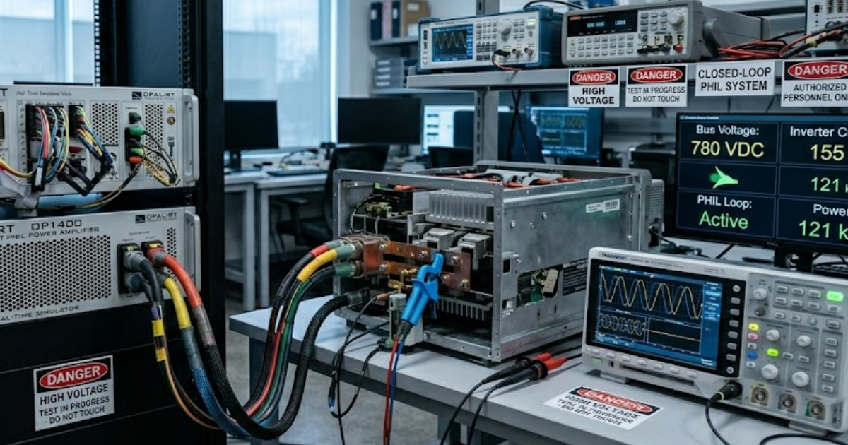
The main difference between PHIL and CHIL is the location of the power stage. CHIL keeps the plant in the simulator and exposes only low-power I/O to the controller. PHIL inserts actual power hardware through a power interface, so voltage, current, and hardware behaviour become part of the closed loop.
A charger programme makes the split easy to see. If the digital signal processor board alone is wired to the simulator, you are working in CHIL. If the actual converter is tied through a power amplifier and measured electrical feedback, you are working in PHIL, because converter losses, limits, and protection timing remain physical.
| If your main validation question sounds like this | Start with this method because it answers sooner |
|---|---|
| I need to prove PWM logic, sequencing, and controller fault handling. | CHIL answers faster because only the controller stays physical and reset time remains short. |
| I need to measure converter loss, saturation, or thermal response under load. | PHIL is required because the power stage itself must remain in the loop. |
| I need safe fault injection that I can repeat many times in one shift. | CHIL keeps risk low and makes repeated edge case testing practical. |
| I need to see trip points shaped by sensor noise and hardware tolerances. | PHIL exposes effects that a clean plant model will smooth over. |
| I do not yet have a stable power interface, isolation plan, or amplifier tuning. | CHIL remains the reliable choice until the PHIL interface is mature enough to trust. |
CHIL fits control validation before power hardware is ready
CHIL fits best when the controller is still the unknown and the power hardware is unfinished, expensive, or unsafe to energize. It lets you validate control timing, supervisory logic, and communications against a high-fidelity plant model long before the full test bench is assembled.
A microgrid controller is a common example. Dispatch logic, breaker sequencing, and voltage regulation can be checked against a digital feeder model months before the power cabinet arrives. That gives the controls team time to fix startup order, limit handling, and message timing while mechanical work and procurement continue. Progress keeps moving even when hardware lead times do not.
That order saves more than the schedule. CHIL will keep software teams productive without exposing the lab to high voltage risk too early. It also gives you cleaner pass or fail signals. If a loop goes unstable in CHIL, the controller design owns the problem, so you are not guessing between code issues and power hardware side effects.
PHIL captures hardware effects that CHIL cannot represent
PHIL matters when the plant model is no longer the limiting factor and the hardware itself can alter the answer. Physical switching, sensor offset, dead time, magnetic saturation, and protection timing will all shape behaviour in ways that a controller only setup will hide or smooth over.
A battery inverter makes this plain. Current ripple, contactor bounce, measurement lag, and component tolerances can shift the response that the controller sees, even when the control code is stable. Renewables are set to meet more than 95% of global electricity demand growth through 2027, so more grid tied equipment now needs validation that includes physical power behaviour under load.
PHIL is built for that stage of the workflow. You connect the actual converter or device under test through a power interface and watch what the hardware does under simulated grid or plant conditions. That is how you catch nuisance trips, unstable damping, or measurement chain quirks before commissioning. PHIL earns its complexity only after the physical power stage becomes part of the question you need to answer.
Interface stability sets the ceiling for PHIL fidelity
PHIL fidelity is limited by the quality of the interface between the simulator and the power hardware. Delay, amplifier bandwidth, sensor latency, scaling errors, and compensation choices will shape the closed-loop response. If that interface is poorly tuned, the test bench will create problems that the hardware itself does not have.
A DC/DC converter loop can look perfect until 150 microseconds of delay sits between simulated source impedance and measured current feedback. Add a slow amplifier or an aggressive interface algorithm and the closed loop will oscillate even though the converter control is sound. PHIL fidelity always sits behind interface design. That single fact explains many failed first attempts.
You need to judge amplifier bandwidth, sensor latency, scaling, and compensation as part of the method itself. A stable setup often starts with a simplified network, reduced fault energy, and carefully tuned interface gains. Teams that skip this work often blame the prototype for problems created by the test bench. CHIL does not carry the same burden, which is why it remains the easier first step.
Electrical risk often decides the method before budget
Electrical risk will usually settle the PHIL or CHIL question before cost spreadsheets do. CHIL keeps most failure energy inside the simulator, while PHIL introduces powered hardware that can fail in milliseconds. If the hazard controls are immature, the technically elegant choice will still be the wrong choice.
“PHIL fidelity always sits behind interface design.”
A protection relay check in CHIL carries little physical consequence when the trip logic is wrong. Put the same logic into PHIL with a live converter and the error can dump fault current into a prototype before anyone can intervene. Safety planning will often decide the method sooner than budget review. Teams that ignore that sequence usually pay for it in retests and damaged hardware.
- Fault energy can damage a prototype in milliseconds.
- Isolation gaps will limit where you can probe safely.
- Protection coordination will shape which tests can run.
- Operator access will shrink once the bench is energised.
- Reset time after a trip will slow iteration sharply.
If several of those points are still unresolved, stay in CHIL longer. PHIL is worth the extra cost only when the unknown lives in powered hardware and the lab can control the hazard. That order keeps teams from burning weeks on repairs, retests, and approval delays. It also protects scarce prototypes that cannot be replaced quickly.
A phased workflow moves teams from CHIL to PHIL
A phased workflow moves from software proof to controller proof and only then to power interaction proof. CHIL should clear control stability, timing, and logic first. PHIL should start after unanswered questions centre on the powered hardware, its sensing chain, or its interaction with the simulated plant.
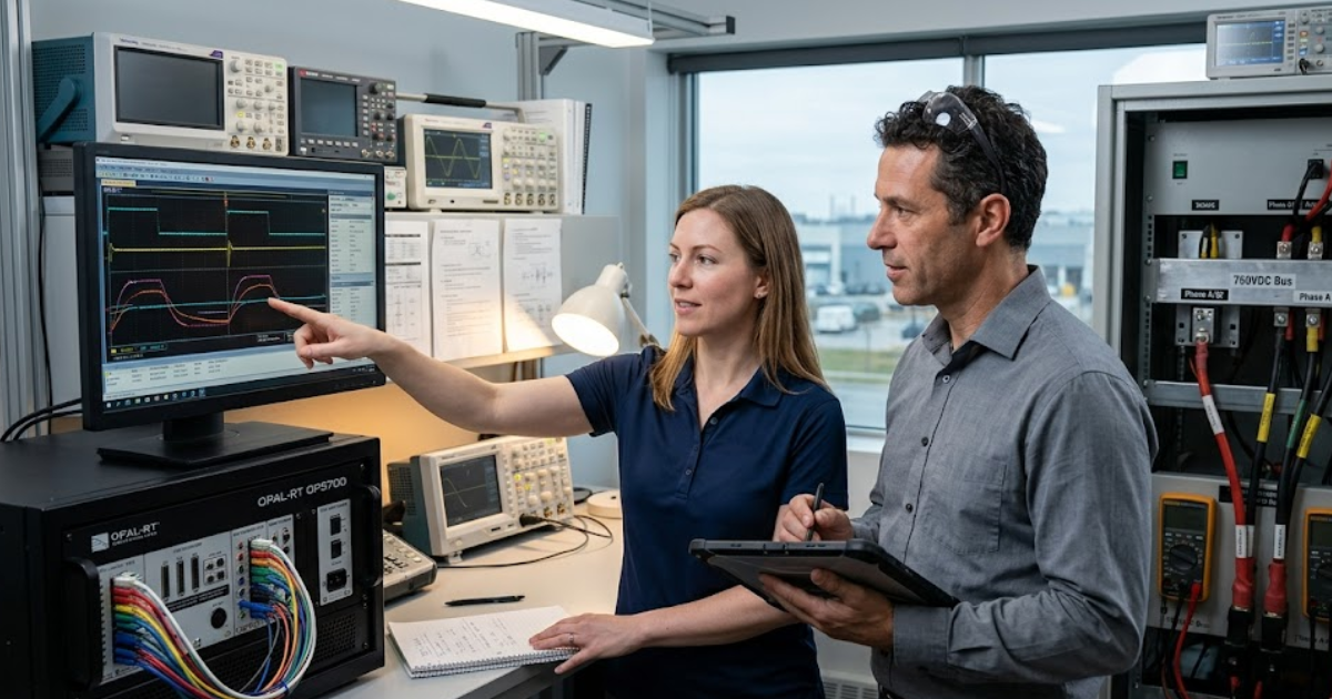
A motor drive programme often starts with model only control design, then moves to CHIL for I/O timing, fault logic, and supervisory code, and reaches PHIL once the inverter or motor hardware is mature enough to test safely. OPAL-RT often sits in the middle of that sequence as the real-time execution layer that keeps models, interfaces, and test scripts aligned. That kind of staging gives each team a clear handoff point.
Each transition needs an exit rule. CHIL should close when control behaviour is repeatable across nominal and fault cases. PHIL should open when open questions centre on power losses, protection edges, sensing lag, or component interaction. That phased method prevents teams from using PHIL as an early debugging crutch and keeps the more complex bench reserved for questions only it can answer.
Common selection errors lead to late test rework
Late rework usually starts with a simple mistake: teams choose a method from habit instead of from the unknown they still need to remove. CHIL will disappoint you if you expect it to expose converter physics. PHIL will waste time if basic control logic still fails under clean simulated faults.
A charger team that jumps straight to PHIL often spends weeks chasing trips caused by unfinished control code. A controls team that stays in CHIL too long will reach the power bench convinced the design is stable, then find that sensor lag or protection timing shifts everything under load. Both paths create rework because the validation question was framed poorly. The fix is disciplined sequencing, not more lab complexity.
The better habit is to ask what remains physical, what remains risky, and what remains unproven. That will tell you where CHIL stops and PHIL starts. Labs that keep that discipline, using OPAL-RT or any other open real-time simulator, build confidence step by step instead of hoping one setup will answer every question. That judgment will save more time than any acronym ever will.
Real-time solutions across every sector
Explore how OPAL-RT is transforming the world’s most advanced sectors.

Simulation
06 / 23 / 2026
Digital twin vs simulation
A practical guide to digital twin vs simulation, with criteria for engineering use, power system examples, and advice on real-time testing and telemetry quality.

Power Systems
06 / 23 / 2026
FPGA-based real-time simulation for Power Electronics
A guide to FPGA simulation for power electronics that explains timing, partitioning, latency, hybrid execution, and toolchain choices for converter testing.

Automotive
06 / 22 / 2026
Vehicle-to-grid technology and what it means for utility distribution planning
A practical review of vehicle-to-grid technology for utility planners, covering feeder effects, hosting capacity models, lab testing, customer participation, and capacity limits.