Why multi-phase machines are becoming increasingly popular
Power Electronics | Power Systems
04 / 29 / 2026

Key Takeaways
- Three-phase motors gain favour when supply fit, torque quality, and wiring flexibility matter more than minimal installation effort.
- Current balance and correct three-phase motor wire connection matter as much as motor size for efficiency and service life.
- Connection diagrams earn their value during commissioning, where phase order and jumper placement shape rotation and fault risk.
Three-phase motors win when you need steady torque, efficient power use, and flexible installation at industrial scale.
Motor systems use about 45% of global electricity, so small efficiency gains matter once equipment runs all day. That helps explain why multi-phase machines keep showing up in plants, labs, and utility assets where load quality matters. Their appeal comes from physics, supply fit, and wiring options that scale cleanly as power rises. That is why users comparing supply options keep landing on the same answer.
Multi-phase machines solve power delivery limits of single-phase systems
Multi-phase machines solve a basic supply problem. They spread power delivery across separate alternating phases, which keeps instantaneous power far more even than a single-phase circuit. That steadier input lets a motor start larger loads, run cooler, and carry useful power without the same level of pulsation.
A shop compressor on single-phase power often needs start capacitors and still struggles under a hot restart. A comparable three-phase electric motor starts with a rotating magnetic field built into the supply itself. That reduces reliance on auxiliary starting parts. You get cleaner torque production from the first turn.
That matters when uptime rests on repeatable starts. Pumps, fans, and conveyors care about not stalling when the line is full. Once load size climbs, single-phase systems stop being convenient and start imposing design penalties. Multi-phase machines remove that ceiling.
“Once load size climbs, single-phase systems stop being convenient and start imposing design penalties.”
Three-phase electric motors produce steadier torque under load
Three-phase electric motors produce smoother torque because each phase takes turns pushing the rotating field. The shaft never falls into the deep torque valleys common with single-phase designs. Under load, that translates into less vibration, quieter mechanical behaviour, and better speed holding.
A belt conveyor carrying boxes shows this difference quickly. A single-phase drive creates stronger torque ripple that can shake couplings and belt tensioners. A three-phase motor keeps force delivery more even across each rotation. Bearings, keys, and gear teeth feel that difference over long duty cycles.
Smoother torque also improves process quality. Mixers hold more consistent agitation, machine tools hold speed more cleanly, and air handling units avoid some pulsing that shows up as noise. You still need proper sizing and alignment, yet the motor starts from a better physical foundation. You feel the benefit in service intervals as much as in process stability.
Higher efficiency starts with current balance across three phases
Higher efficiency in a three phase motor depends on balanced voltage and balanced current. When each phase shares work evenly, copper losses stay lower and heat stays manageable. Once one phase drifts, the motor still turns, but it wastes energy and shortens insulation life.
A loaded pump motor makes this easy to see. A small supply imbalance pushes current higher in one winding, and temperature rises faster than many teams expect. A 3.5% voltage unbalance can raise motor temperature by 25%. That extra heat eats service life long before the nameplate looks exceeded.
You cannot judge efficiency from motor size alone. Cable length, loose terminals, uneven supply, and poor phase loading all alter the result. That is why current balance deserves attention before anyone blames the motor design. The best machine in the wrong electrical conditions will not deliver the efficiency you paid for.
Three-phase motors match the power supply used in industry
Three-phase motors fit industrial power systems because most large facilities already distribute a three-phase supply to feed equipment, heating, and drive loads. That alignment cuts conversion steps and avoids the compromises of forcing single-phase motors into jobs that need higher power or frequent starts.
A water treatment site is a clear case. Incoming service supports pumps, blowers, and variable frequency drives across a common three-phase bus. Installing a single-phase motor there adds no benefit and can complicate protection, starting, and spare parts. Matching the motor to the available supply keeps the design simpler.
Supply infrastructure shapes motor choice as much as motor physics does. Once your building, plant, or test bench is wired for three-phase service, the practical answer is often a three-phase motor. That fit reduces panel complexity and keeps maintenance practice consistent across the site. You remove workarounds before they show up in commissioning.
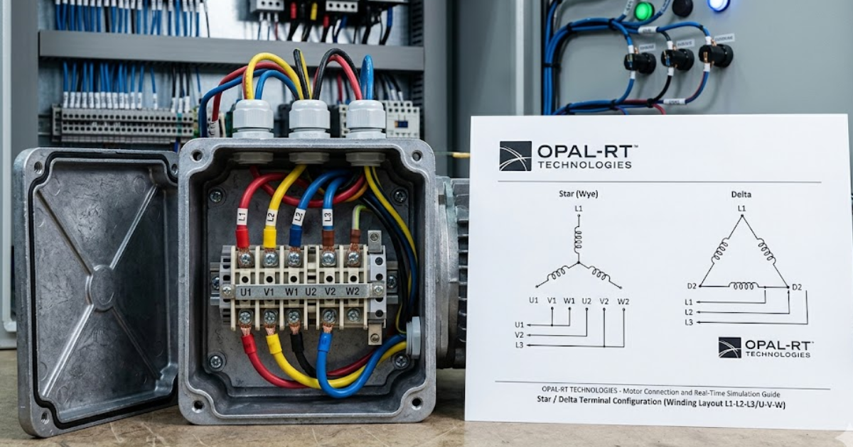
Three-phase motor wire connection sets voltage compatibility
The three-phase motor wire connection determines what line voltage the windings actually see. A six lead motor can often be linked in star or delta, and that choice decides whether the motor suits a higher or lower supply. The connection sets compatibility from the start.
A common case is a dual voltage motor rated for 230/460 V. The same machine can be wired one way for a lower voltage supply and another way for a higher supply, as shown in the nameplate and the three-phase motor wiring diagram. If you ignore that mapping, current rises sharply and protection trips quickly. Voltage fit depends on jumper placement as much as on motor rating.
You should treat the motor connection diagram three-phase data on the nameplate as operating instructions. Reading it casually creates avoidable errors. Lead numbers, jumper positions, and supply voltage all have to agree. Guesswork is what turns a sound motor into a burnt one
| Wiring situation | What it tells you before power is applied |
|---|---|
| Dual voltage nameplate | The nameplate shows which jumper pattern matches 230 V and which pattern matches 460 V. |
| Star connection selected | This setup suits higher line voltage because each winding sees lower phase voltage. |
| Delta connection selected | This setup suits lower line voltage because each winding sees full line voltage. |
| Phase groups linked incorrectly | A misplaced link will raise current, trip protection, or overheat the motor within minutes. |
| Nameplate data unclear | You should stop and confirm the manufacturer data before any energization step. |
Motor connection diagrams matter because phase order affects rotation
Motor connection diagrams do more than show where wires land. They also protect rotation direction, starter logic, and the relationship between the motor and the machine it drives. Swap any two incoming phases and the motor will reverse, which is harmless in some cases and costly in others.
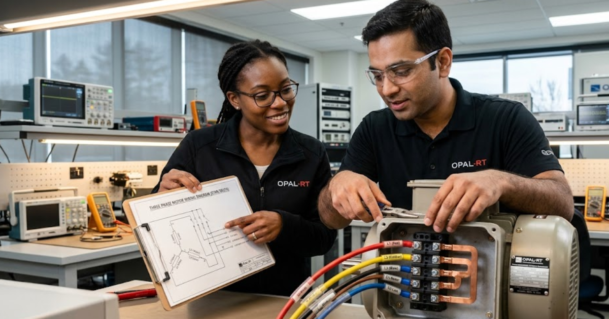
A centrifugal pump run backward will still spin, yet flow collapses and seals can suffer. A hoist or conveyor can create a direct safety problem if rotation goes the wrong way after maintenance. Teams using a real-time simulator such as OPAL-RT can verify phase sequence, drive logic, and protection response before field wiring is locked. That step helps separate wiring risk from machine risk.
Diagrams deserve a functional reading. You are not only matching terminal numbers or placing links under screws. You are validating how the motor interacts with the load and control chain. A quick uncoupled bump test is cheap insurance.
Wiring mistakes explain many three-phase motor startup faults
Most three-phase motor startup faults come from wiring errors, not failed steel or copper. Wrong jumper placement, weak terminals, missing overload settings, and reversed phase sequence can all stop a healthy motor from starting correctly. The usual fix is a disciplined check of connection details before reenergizing.
A stalled motor after installation often points to a small mistake made early in the job. The fastest checks are simple, and they catch many avoidable issues before deeper testing begins.
- Confirm supply voltage matches the nameplate connection.
- Check every jumper against the terminal diagram.
- Tighten terminals to the specified torque.
- Verify overload and breaker settings against full load current.
- Bump test rotation before coupling the load.
These checks save time because they separate wiring faults from motor faults. They also protect mechanics who might otherwise chase couplings, bearings, or process problems that started electrically. Good startup work is quiet and methodical. Rushed commissioning turns minor wiring slips into avoidable downtime.
“You hear it in lower vibration, see it in steadier current, and notice it when wiring options match the supply on hand.”
Multi-phase machines justify extra complexity in high-duty roles
Multi-phase machines justify their added wiring detail when duty is heavy, starts are frequent, or process stability matters. You accept a bit more installation discipline in exchange for smoother torque, better efficiency, and easier alignment with industrial supply. That trade is usually worthwhile once power and runtime increase.
A small bench grinder in a light shop can live happily on single-phase power. A compressor bank, process pump, or traction test stand cannot ignore torque ripple, heat, or awkward starting methods for long. Teams building and validating those systems often need to test the motor, drive, and protection as one chain, which is where platforms from OPAL-RT fit naturally in lab work. That kind of preparation keeps wiring details from becoming system faults.
Popularity follows performance that people can feel in service. You hear it in lower vibration, see it in steadier current, and notice it when wiring options match the supply on hand. Engineers trust systems that behave the same way every shift. Multi-phase machines are not simpler on paper, yet they make the total system easier to run well.
Real-time solutions across every sector
Explore how OPAL-RT is transforming the world’s most advanced sectors.

Simulation
06 / 17 / 2026
6 Types of HIL testing
An overview of 6 types of HIL testing that explains open-loop, closed-loop, signal-level, power-level, fault-injection, and distributed setups, plus how to choose the right HIL test bench.

Power Systems
06 / 15 / 2026
How to test OT cybersecurity for power grid SCADA and control systems
A practical guide to OT cybersecurity testing for power grid SCADA and control systems, with focus on NERC CIP evidence, substation trust boundaries, and cyber physical test methods.

Simulation
06 / 14 / 2026
Robotics simulation for research labs moving from concept to hardware validation
This guide explains how research labs use robotics simulation, sensor simulation, and embedded systems simulation to validate robot controls before hardware bench testing.