Real-time simulation of multilevel converters and cascaded topologies
Industry applications, Simulation
03 / 25 / 2026
Key Takeaways
- Real-time multilevel converter simulation depends on partitioning the model around timing limits, not treating every subsystem with the same solver and step size.
- Cascaded H-bridge topologies become difficult when switching density, coupling, and control interactions pile up across cells, transformers, rectifiers, motors, and sensors.
- Useful hardware in the loop workflows focus on repeatable fault coverage, controller timing, and scalable bench reuse across many operating scenarios.
Real-time EMT for multilevel converters works only when you stop treating the whole model as one uniform problem and start assigning each part to the computation method it actually needs. Multilevel converter use is rising with electrification and converter-based generation, and global annual renewable capacity additions reached 666 GW in 2024, which keeps pushing power electronics into larger and more complex grid and industrial systems.
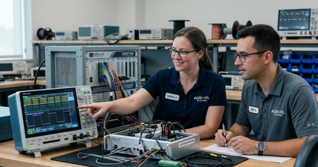
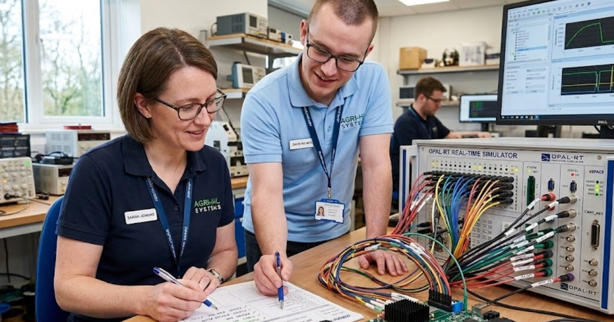
You’re not trying to simulate a diagram. You’re trying to close a timing budget while preserving switching detail, control response, protection logic, and test coverage. The Harvest story shows why that matters in practice: once cascaded cells, phase-shifted transformers, rectifiers, motors, and sensor models sit in the same test bench, architecture choices decide if the model runs in real time or misses every deadline.
“Real-time simulation of multilevel converters starts with a partitioning problem, not a software selection problem.”
Multilevel converter structures create unique computational challenges for real-time EMT simulation
Multilevel converter models become hard to run in real time because the problem is not only switch count. Timing pressure comes from the combination of many semiconductor events, tightly coupled electrical nodes, and control interactions that must all resolve inside a fixed step.
A two-level inverter often lets you simplify switching detail or absorb some dynamics into averaged behaviour. A cascaded or modular multilevel structure does not give you that freedom once you need controller validation, fault logic, or waveform fidelity. Each added cell introduces more states, more gate events, and more points where numerical coupling can slow the solver or distort the result.
That matters most when you need the simulator to talk to an actual controller through fast I/O. Missing one step is not a small modelling error. It breaks the closed-loop test. Engineers run into this when a bench that looked stable in offline simulation starts dropping deadlines as soon as cell balancing, dead time, sensor feedback, and protection logic are turned on. Real-time simulation of multilevel converters starts with a partitioning problem, not a software selection problem.
Cascaded H-bridge converters increase switching interactions and model state complexity
Cascaded H-bridge simulation gets difficult because each cell behaves simply on its own, but the full phase does not. Phase shifting, PWM coordination, and shared control objectives create a dense set of interactions that multiply the computation burden.
The Harvest story gives a concrete picture. A typical 3-phase 8-chain system includes 24 3-phase full-bridge modules, up to 96 switches, more than 100 model states, and dozens of electrical connections across the transformer secondary and rectifier section. That is not a large model because any one block is exotic. It is large because every block must stay synchronized.
You’ll see the impact first in solver stability and then in timing margin. One missed assumption about coupling can force a smaller step size across the whole model, even when only part of the topology needs that resolution. That is why cascaded H-bridge simulation usually fails when engineers build it as a single monolithic EMT model. Complexity is structural, so the solution must also be structural.
Switching frequency, module count, and phase shifting define simulation timing limits
Real-time timing limits are set by three variables more than any others: switching frequency, number of modules per phase, and how phase shifting spreads switching events over time. Those three factors decide how often the solver must react and how much electrical detail it must preserve at each instant. Design that looks moderate on paper can still overwhelm a real-time target. The issue is event density, not only nominal carrier frequency.
The checkpoint below shows how the main timing drivers affect model choices.
| What you’re modelling | What usually sets the timing limit | Best execution target | What happens if you group it with everything else |
| Cascaded inverter cells with detailed switching | Each gate event must resolve without missing commutation detail | FPGA execution usually fits best | The whole model gets forced into a smaller step than most subsystems need |
| Phase-shifted transformer and rectifier coupling | Strong electrical coupling raises solver burden even at lower switching rates | CPU execution with a partitioned EMT solver often works | Solver load rises sharply and timing margin disappears |
| Motor and encoder feedback paths | Closed-loop controller tests need deterministic latency and clean signal timing | Mixed execution with fixed I/O timing is often the safest route | Control validation becomes unreliable even when waveforms look plausible |
| Protection faults and abnormal operating points | Sudden topology changes create short bursts of heavy computation | Partitioned real-time EMT is usually required | Fault tests become the first place where deadlines are missed |
| Large system networks around the converter | Network size adds states that do not all need nanosecond detail | CPU execution at a slower rate is usually more efficient | Expensive hardware gets consumed solving slow electrical behaviour |
Partitioning converter, transformer, and rectifier models across CPU and FPGA execution
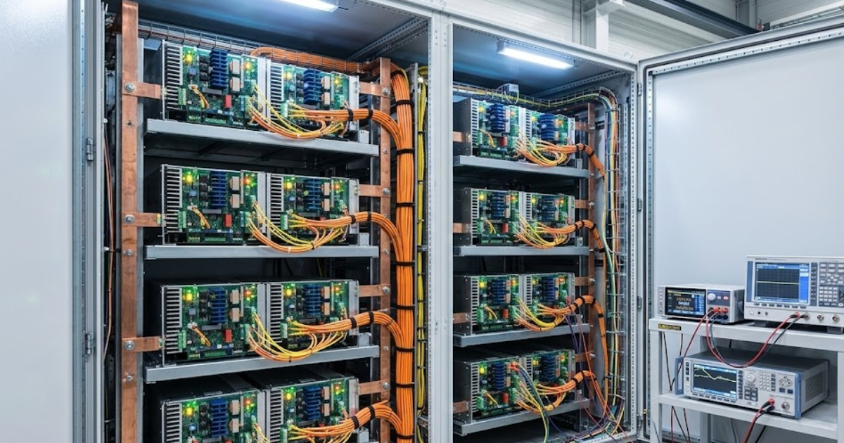
Good model partitioning separates what must switch fast from what must remain electrically broad and well coupled. Converter cells belong where event timing is cheapest to preserve, while transformers, rectifiers, and wider networks belong where larger matrices and slower dynamics are easier to solve. A practical setup often places the cascaded inverter on FPGA hardware and keeps the front-end transformer and rectifier on the CPU with a partitioned EMT solver.
Platforms such as OPAL-RT are built around that split because no single processor type handles every part of a multilevel converter model equally well. Partitioning also protects your budget. Sending everything to FPGA hardware wastes resources on subsystems that would run accurately on the CPU, while sending fast switching cells to the CPU usually destroys timing margin. The right split is not about prestige hardware. It is about assigning cost and fidelity where they actually matter.
FPGA execution handles high switching frequency power electronics models
FPGA execution is the practical answer when converter detail must stay explicit at very small time steps. That is especially true for multilevel inverters, where switching behaviour, interleaving, and dead time create timing patterns that standard CPU execution will not hold under real-time constraints.
A strong example is a cascaded H-bridge inverter model used for controller testing with detailed gate signals, capacitor voltage balancing, and protection events. FPGA-based execution for power electronics models at time steps down to the nanosecond level and support for switching frequencies above 200 kHz. That does not mean every multilevel model needs nanosecond resolution. It means the hardware can preserve it when the test objective requires it.
Industry pressure makes that capability more important. Industry accounted for nearly 40% of total final energy demand in 2024, which helps explain why larger motor drives, converter-fed systems, and electrified process equipment keep getting more attention. When you need explicit switching and deterministic latency, FPGA execution will carry the part of the model that sets the real-time limit.
CPU solvers simulate slower electrical subsystems and large network interactions
CPU solvers still matter because much of a converter system does not need ultrafast switching detail. Slower electrical subsystems, wider networks, and strongly coupled passive elements often run more efficiently on the CPU, especially when the solver can partition the model without adding artificial delay.
Subsystems do not require high-frequency switching, so tens of microseconds were sufficient, yet the solver still had to decouple more than twenty converters from a multi-winding transformer to stay within real-time limits. That is a classic CPU job. The model is electrically large, but not every part is event-dense.
You’ll get better results when you let the CPU carry what it is good at. Large passive networks, grid interfaces, machine models, and slower converter stages often belong there. A good CPU EMT solver also gives you multi-rate execution, which means you are not paying nanosecond costs to simulate millisecond behaviour. That split preserves fidelity where you need it and keeps hardware use sensible.
Hardware in the loop testing validates multilevel converter control strategies
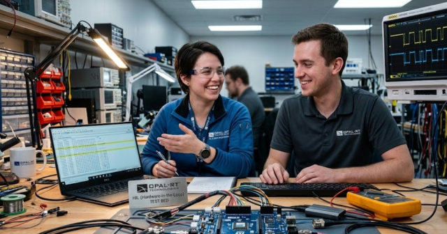
Hardware in the loop testing matters because the goal is not only waveform reproduction. You need proof that the actual controller behaves correctly when it sees realistic switching states, machine feedback, and abnormal operating conditions.
Control verification for variable frequency control and vector control on asynchronous and permanent magnet synchronous motor applications, along with fault-condition tests for grounding protection, out-of-phase detection, and bus overvoltage or undervoltage events. Those are the kinds of tests that expose timing bugs, protection mistakes, and sequencing problems that offline simulation will miss.
Five test scenarios usually deserve attention first:
- single-cell misfire and gate timing mismatch
- DC-link or bus overvoltage protection response
- motor type swaps on the same control bench
- grounding or output fault detection under load
- controller recovery after mode or reference changes
Each one forces the controller to respond to a condition that is awkward, costly, or unsafe on a physical high-power prototype. That is why hardware in the loop testing is not an extra validation layer. It is the point where multilevel converter simulation becomes an engineering tool instead of a modelling exercise.
Simulation workflows that scale cascaded converter testing across many operating scenarios
“Teams that follow that discipline get reliable results sooner, spend less time chasing solver limits, and make better judgments about what still needs physical testing.”
Scalable cascaded converter testing comes from disciplined execution, not from building the largest possible model. You need a workflow that reproduces site issues quickly, swaps machines and sensors without rebuilding the bench, and keeps the controller under test connected to the same timing rules every time.
There is significant value in an approach that uses one-bench multi-motor testing, earlier defect exposure, fault-condition coverage, and lab reproduction of site issues, without repeated travel or full-power prototype setup. Those gains come from choosing the right abstraction for each subsystem and keeping the test workflow repeatable.
That is also where OPAL-RT fits naturally in practice. The useful point is not the brand itself. The useful point is the execution model: split fast converter physics from slower network behaviour, keep I/O deterministic, and build benches that your team can extend without redoing the entire architecture.
Real-time solutions across every sector
Explore how OPAL-RT is transforming the world’s most advanced sectors.
Simulation
03 / 25 / 2026
Integration testing between firmware and physical interfaces
Covers how to plan and run firmware integration testing for physical interfaces using staged loops, HIL protocol simulation, tool selection, and trace-based debugging for CAN and similar buses.

Simulation
03 / 23 / 2026
Scaling from academic HIL setups to industrial validation platforms
Practical guidance for moving an academic HIL system from an entry level FPGA real time simulator to a modular platform that supports scalable real time simulation, repeatable tests, and traceable industrial validation results.
Industry applications, Power Systems
03 / 22 / 2026
AI workload variability and its impact on data center power stability
This piece explains how AI workload patterns affect data centre power stability and how engineers model and test those effects with converter-aware, real-time methods.
EXata CPS has been specifically designed for real-time performance to allow studies of cyberattacks on power systems through the Communication Network layer of any size and connecting to any number of equipment for HIL and PHIL simulations. This is a discrete event simulation toolkit that considers all the inherent physics-based properties that will affect how the network (either wired or wireless) behaves.