When FPGA real time simulation makes sense for power electronics HIL
Simulation
01 / 22 / 2026
Key Takeaways
- Timing determinism is the main reason to choose FPGA real time simulation for power electronics HIL.
- Averaged and CPU models fit best when pass or fail depends on slow dynamics and steady values.
- Partitioning, I/O latency budgets, and repeatable fault tests will decide practical success.
FPGA real time simulation makes sense for power electronics HIL when switching behaviour and protection timing must match your controller. Electric car sales neared 15 million in a recent IEA report, which raises the volume of inverter and charger validation work in many labs. A test that misses a fast event will still look clean on plots. That false confidence is expensive.
CPU real time simulation still earns its place for many converter and drive tasks. Problems start when you need switching level detail and fixed I/O timing at the same time. Averaged models can hide the exact edge case you are chasing. FPGA real time simulation is the practical choice when timing decides pass or fail.
What FPGA real time simulation actually solves for power electronics
“FPGA real time simulation solves timing determinism, not only model detail.”
It runs the time critical electrical network in fixed steps. It keeps I/O latency stable, so your controller sees the same delay every run. That repeatability makes HIL results comparable across builds and teams.
A PWM inverter test shows the benefit quickly. Gate commands from the controller hit the simulated switches with no scheduling jitter. Current feedback returns on time, so sampling and PWM stay aligned. A protection path, like an overcurrent trip, will trigger at the same instant each run.
Deterministic timing matters when you debug unstable behaviour at high duty cycles. A CPU that occasionally overruns will blur event order and waste lab time. FPGA partitioning also stays focused, so you only move the fast parts onto the FPGA. Slower parts, like mechanical load or thermal response, can stay on CPU without hurting the timing chain.
Why CPU based real time simulation fails for fast switching converters
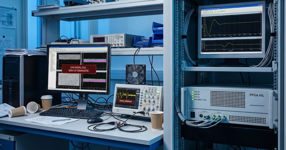
CPU based real time simulation fails when the model needs tiny steps and strict I/O timing. A CPU shares cycles across tasks and will introduce jitter. That jitter forces larger steps or simplified switching detail. The plant then reacts late even if it looks smooth.
A clear symptom appears when you compare an averaged inverter model to a switching model on the same CPU. The switching model will slow down until ripple and peak currents are muted. Hardware protection will trip on the bench, but the simulated plant will miss the same trigger. Your team ends up tuning around a simulator artefact instead of a control issue.
CPU simulators still work well for slower dynamics, such as DC bus energy balance or speed loops. The problem is time scale, not solver quality. Switching transients can fall into nanoseconds, with a measured turn-on time of 11.4 ns in a SiC MOSFET test. Once your test depends on events that fast, deterministic scheduling matters more than raw floating point throughput.
When FPGA real time simulation is the right choice
“Judgement still matters more than raw model fidelity.”
FPGA real time simulation is the right choice when timing links your controller, measurements, and protection logic. It fits power electronics HIL where microsecond delays change the control outcome. It also fits motor drives where PWM, sampling, and fault logic interact inside one cycle. Timing will stay fixed run to run.
Five signs your plant belongs on FPGA:
- Protection logic depends on exact trip and reset timing.
- Current feedback needs fixed latency and low jitter.
- PWM and sampling instants must stay aligned each cycle.
- Tests require repeatable switch faults and short circuits.
- Switching cannot be averaged without losing meaning.
Bench risk is a good example. A short circuit test on hardware will stress devices and vary run to run. A simulated short circuit will repeat exactly, so you can verify trip handling and recovery logic. An open switch fault test will also confirm the controller’s fallback mode.
Scope discipline keeps the work practical. Put the switching network and fast measurement chain on FPGA, then keep slower parts on CPU. That split avoids forcing every subsystem into fixed point logic. It also keeps your HIL setup maintainable across control revisions.
Key technical criteria that justify FPGA over averaged models
Choosing FPGA over an average model depends on what you must observe and trigger. Averaged models work when mean values over many switching periods are enough. Switching models are justified when discrete states and event timing affect stability, limits, or faults. Test intent sets the model choice.
A buck converter shows the split. An averaged model will tune the voltage loop and check soft start. That same model hides current limit chatter and diode conduction changes that trip protection. A motor drive has the same issue when phase current peaks matter.
| What you need to prove | Averaged model fits when | FPGA switching fits when |
| Current limit and trip behaviour | Trip uses filtered current | Trip uses instant peaks |
| PWM and sampling alignment | Timing offset is harmless | Timing offset changes loop |
| Fault handling and restart | Fault path is slow | Fault timing sets recovery |
| Switch state transitions | Ripple details are irrelevant | Switch states change currents |
| High bandwidth loop behaviour | Ripple stays outside loop | Ripple destabilizes loop |
Write pass or fail statements first. Event order or peak values will break an averaged model. Discrete switch states will also break it. Steady values and slow dynamics fit averaging.
How FPGA based HIL improves converter and motor drive validation
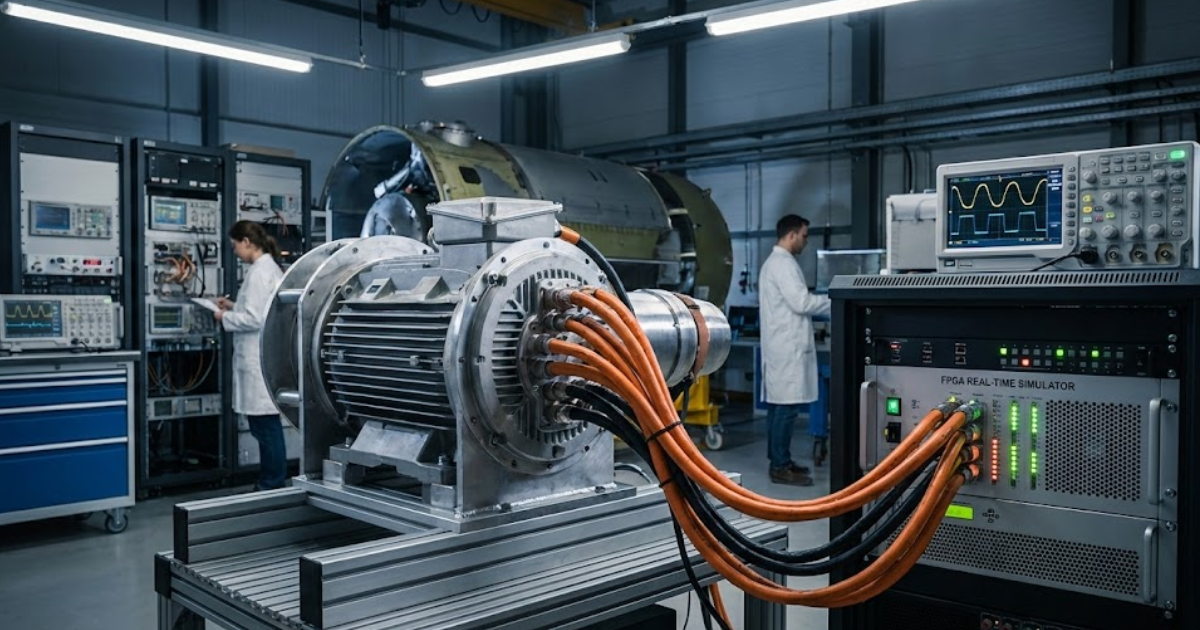
FPGA-based HIL improves validation because you can repeat timing, faults, and measurements exactly. You can run the same script and isolate what changed in the controller. You can also test failure behaviour without risking power hardware. That makes results useful for both engineers and leads.
Start with the sensor chain in a motor drive test. You can inject a phase current offset, a stuck position signal, or a DC bus sag, then watch observer behaviour and limits. You can also force an open switch fault on one leg and confirm the controller moves into a safe mode. Many teams run the switching network on FPGA using eHS and integrate the full setup on OPAL-RT so the I/O path stays deterministic.
Repeatability is the main payoff. A bench short circuit is risky and hard to reproduce, and data quality depends on probe setup. A simulated fault is consistent, so you can verify trip handling, logging, and recovery logic across many iterations. You still need scaling checks and sanity comparisons to bench data, but the validation cycle becomes far less noisy.
Common misconceptions about FPGA complexity and usability
FPGA complexity gets exaggerated when it is treated as an all-or-nothing rewrite. Most converter and drive models do not belong entirely on FPGA. A focused partition will map only the time critical electrical parts to FPGA logic. Usability then comes from modelling choices, not heroics.
Teams often stall after trying to pack the whole system into one FPGA image. Fixed point choices, scaling, and interface logic grow quickly and hide bugs. A better pattern keeps the fast switch network on FPGA and leaves mechanical load, thermal effects, and supervisory logic on CPU. That split also makes debugging cleaner, because timing issues and control issues are not tangled.
The work is strict but predictable. You will define numeric ranges, saturation behaviour, and limits so the FPGA stays stable. You will also budget latency so ADC and DAC timing matches controller sampling. Once those rules are set, iteration becomes steady and test results stop drifting.
How advanced multiphase machines push FPGA simulation requirements
Multiphase machines push FPGA requirements because phase count multiplies computation and fault cases. Electromagnetic coupling between phases adds interactions that averaged drive models hide. Fault tolerant control also depends on phase resolved currents and voltages, not only torque and speed. FPGA parallelism keeps these coupled updates stable at the time scale your controller uses.
Consider an electromagnetically coupled twelve-phase PMSM test with phase loss and reconfiguration logic. You can drop a phase group, change current references, and confirm torque stays within limits without runaway currents. You can also simulate a sensor failure on one phase set and verify the controller still tracks speed. Those tests are hard to run safely on hardware, because faults stress the machine and inverter.
Judgment still matters more than raw model fidelity. Clear pass or fail criteria and disciplined timing budgets will decide if HIL work pays off. OPAL-RT teams that run coupled multiphase machine models on FPGA get the best results when model partitioning, I/O timing, and repeatable fault scripts are treated as first-class engineering tasks. That focus will keep your results actionable and your lab time well spent.
Real-time solutions across every sector
Explore how OPAL-RT is transforming the world’s most advanced sectors.

Industry applications, Simulation
03 / 31 / 2026
Managing high-frequency switching in real-time EMT simulation
Precision in testing complex power systems is essential to avoid failures, accelerate innovation, and integrate new technologies safely.

Simulation
03 / 30 / 2026
Understanding timestep requirements for modern power converters
Practical criteria for selecting EMT and real time simulation timesteps for power converters, covering switching resolution, control and PWM timing alignment, multirate approaches, and verification checks.

Industry applications, Simulation, Energy
03 / 29 / 2026
Validating data center energy management systems using real-time HIL
This piece explains how AI workload variability affects data centre power stability and how closed-loop HIL testing helps validate EMS control behaviour under site and grid stress.
EXata CPS has been specifically designed for real-time performance to allow studies of cyberattacks on power systems through the Communication Network layer of any size and connecting to any number of equipment for HIL and PHIL simulations. This is a discrete event simulation toolkit that considers all the inherent physics-based properties that will affect how the network (either wired or wireless) behaves.