A complete guide to hardware-in-the-loop testing for power systems engineers
Power Systems
06 / 12 / 2025
Key Takeaways
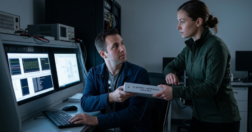
- Protection settings prove out before any DER controller enters the loop, so a coordination margin that shifts on the second pass belongs to the DER and nothing else.
- Stage ownership and versioned handoff packages between planning, protection engineering and operations decide how far a utility HIL programme actually gets.
- Running IEC 61850 and IEEE C37.118 against one grid model lets protection and control room groups read a single event record instead of two reconstructions.
Utilities get trustworthy protection and DER interconnection answers when hardware in the loop testing runs as a sequenced programme instead of a set of isolated bench sessions.
The queue keeps growing. Roughly 2,060 GW of generation and storage was actively seeking transmission interconnection across the United States at the end of 2025. Each project eventually becomes a setting to check, a model to validate, or a controller to accept. Bench time can’t scale the way a queue does, so the order of operations becomes the constraint.
A relay bench answers questions about one device. A utility HIL workflow answers questions about a study that started in planning, moved through protection engineering, and finishes with operations accepting a new feeder resource. One simulation model carries all three conversations, and getting the handoffs right does more for schedule than any single clever test case.
What a utility HIL programme covers beyond a single relay test
A utility HIL programme covers four things a single relay test doesn’t. It validates the network model, the protection settings applied to it, the DER controller responses under the same fault set, and the operating procedures that follow a trip. All four run against one real time simulation of the same feeder.
A distribution planning group usually starts with a short circuit study of a 12.47 kV feeder carrying a new 5 MW solar site, which says fault current at the recloser drops once the site is online. Turning that into a bench case means rebuilding the feeder as an electromagnetic transient model, wiring the recloser control and the site’s relay into the loop, then replaying the faults with the site online and offline.
Those four targets fail differently and belong to different people. A model error shows up as fault current that doesn’t match field records. A settings error shows up as a relay that trips correctly but too slowly. A controller error appears only when the DER rides through a voltage dip. Running all of it on one bench lets you tell those failures apart.
Sequencing protection validation and DER interconnection on one bench
Protection validation comes first and DER interconnection validation comes second, because the DER cases depend on settings that are already proven. Running them the other way around means every DER result carries an unverified settings assumption, and a failed case tells you nothing about which layer broke.
Picture a substation with a new 20 MW battery site behind the same 25 kV bus as three existing feeders. The protection stage replays close-in and remote faults against the bus differential and the feeder overcurrent elements with no DER contribution, confirming coordination margins hold. Only after that pass clears does the battery controller come into the loop. Any margin that shifts on the second run is attributable to the DER, which is worth the extra day of bench time.
“Protection validation comes first and DER interconnection validation comes second, because the DER cases depend on settings that are already proven.”
Who owns each stage and what gets handed between groups
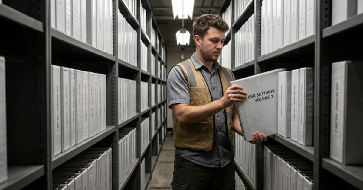
Planning owns the network model, protection engineering owns the settings and the fault set, and operations owns the acceptance criteria and the switching procedures. Each group hands the next a defined package rather than a file drop, and those handoff points are where utility HIL programmes usually stall.
A workable handoff package between those groups holds five things.
- The validated network model with source impedances and line parameters matched to field records
- The agreed fault set, listing locations, types and durations approved before bench time
- The relay settings file exactly as it will be loaded into the field device
- The DER controller configuration including ride-through curves and the firmware build under test
- The pass criteria written as measured quantities such as trip time and voltage recovery
Firmware build is the item most often left out, and it’s the one that causes the worst surprises. A settings file that passed in March will behave differently on a device shipped with a later build in July. Planning owes the same courtesy upstream, handing over the source impedance it used so protection engineering isn’t reverse engineering a fault current later.
“Each group hands the next a defined package rather than a file drop, and those handoff points are where utility HIL programmes usually stall.”
Where power hardware in the loop fits against controller HIL
The main difference between power hardware in the loop and controller hardware in the loop is what crosses the boundary. Controller HIL exchanges low level signals and messages with a relay or controller, while power HIL pushes actual current and voltage through an amplifier into physical equipment. Utilities use both, at different stages.
Relay and DER controller acceptance runs almost entirely on controller HIL. A protection engineer validating a distance element sends analogue secondary quantities and status points to the relay, then reads the trip contact back. Power HIL earns its place when the item under test sources or absorbs real power, such as a full converter, where behaviour under load is the question.
| Validation stage | How the two forms of HIL divide the work |
| Network model confidence | Controller HIL settles this against recorded field events, and power HIL adds nothing here |
| Relay settings and coordination | Controller HIL proves trip times and margins at signal level for a device drawing little power |
| DER controller acceptance | Controller HIL checks ride-through and mode transitions, and power HIL confirms them at rated current |
| Anti-islanding and reconnection | Controller HIL verifies detection timing, and power HIL shows unit behaviour at full output |
| Operating procedure rehearsal | Controller HIL lets crews rehearse restoration, and power HIL reproduces the inrush crews will see |
Cost decides the split. Power HIL needs an amplifier sized to the equipment, plus safety interlocks and floor space, so most utilities own one power capable bay and several controller positions. Most protection and DER questions get answered at signal level.
How IEC 61850 and IEEE C37.118 carry relay and PMU traffic
IEC 61850 carries the protection traffic and IEEE C37.118 carries the synchrophasor traffic. GOOSE messages move trip and block signals between the simulator and the relay in milliseconds, sampled values carry the digitized current and voltage, and C37.118 streams time stamped phasors to the wide area application under test.
A substation built around a process bus gives the bench a clean job. The simulator publishes sampled values onto that bus, the relay subscribes exactly as it would in the field, and the trip GOOSE returns to the simulator to open the modelled breaker. Nothing about the relay configuration changes between bench and substation, which is the point.
PMU traffic serves a different purpose on the same bench. C37.118 streams let you replay a fault or a DER trip into a state estimator and see what control room staff would have seen. HYPERSIM holds the grid model while those two protocol stacks carry the relay and PMU interfaces, so protection and operations read one event rather than two reconstructions of it.
Common failure modes that surface late in utility HIL programmes
Late failures come from settings that were never validated against equipment capability, models that don’t match the field, and handoffs that lost a version number. All three are cheap to catch on a bench and expensive to catch after energization.
Inverter protective settings are the clearest case. A single 500 kV phase-to-ground fault in March 2024 removed 1,046 MW of solar and wind output across 28 facilities in the Western Interconnection, and the review that followed found fewer than one-third of reported inverter settings matched the equipment’s actual capability. A ride-through case against the real controller shows immediately if a unit drops out well inside its rated withstand.
Model mismatch surfaces later and hurts more. An optimistic simulated source impedance makes every coordination margin proved on the bench wrong in the same direction, and you won’t find out until a real fault arrives. Version drift is the third one. A settings file, a controller configuration and a firmware build each carry a version, and a programme that doesn’t record all three will validate something the field never receives.
Making the workflow hold up across successive project cycles
A utility HIL workflow holds up over years when the model, the fault set and the pass criteria are maintained as standing assets rather than project leftovers. Each new interconnection then starts from a validated base instead of a fresh build, and bench hours per project fall.
Utilities that get this right aren’t running more tests. They’re running the same tests against a model that keeps getting better, with handoff packages that carry version numbers and one shared event record. The discipline pays off in the second year, when a new DER application takes two weeks instead of two months.
That’s the argument for building the programme around one simulation platform rather than a shelf of disconnected benches. OPAL-RT users tend to arrive with one relay question and stay because the same model and the same protocol interfaces keep answering the next one. The value isn’t in any individual test. It’s in never having to rebuild the ground underneath it every time a project starts.
Power Electronics
09 / 30 / 2026
FPGA simulation for power electronics and motor drives
A technical comparison of CPU and FPGA solver architectures for power electronics and motor drive simulation, covering the timestep each reaches and how to split a model between them.
Power Electronics
09 / 29 / 2026
How to model and control a T-type three level inverter
An engineering overview of the T-type three level inverter leg, covering how it reaches three voltage levels, where device stress lands, and how neutral point balancing and modulation shape control.
Simulation
09 / 28 / 2026
How CHIL signal-level testing validates embedded controllers
A practical look at signal level controller hardware in the loop testing, covering I/O ranges, sensor emulation, latency and the setup checks that make embedded controller results trustworthy.