
Key Takeaways
- IEEE 1547-2018 compliance depends on measured DER behaviour during abnormal grid conditions, not on simple trip performance alone.
- Type evidence, bench fidelity, and timing accuracy must line up before utility-specific verification can move smoothly.
- Settings control is the weak point in many projects because approved test results lose value when field configuration drifts.
Meeting IEEE 1547-2018 means proving that your DER will stay connected, respond correctly, and trip only when the grid condition truly requires it.
Simple disconnect logic no longer satisfies utility reviewers because feeders need DER that can ride through short disturbances and follow validated settings. More than 2,600 GW of generation and storage sat in United States interconnection queues at the end of 2023, which shows why predictable inverter behaviour matters well beyond a single site. If your test plan doesn’t cover abnormal voltage, frequency, timing, and settings control, approval will stall. You need a sequence that starts with type evidence and ends with site proof.
“You are no longer proving that a DER disconnects safely. You’re proving that it stays useful to the grid until the standard says it must leave.”
IEEE 1547 compliance means proving behaviour across abnormal grid conditions

IEEE 1547 compliance means your DER must behave correctly when the grid moves outside nominal conditions. Passing results will show more than basic protection. They will show measured responses to voltage, frequency, and islanding events. Utilities expect this behaviour to be repeatable and clearly documented.
A practical case is a solar inverter on a feeder that sees a short voltage sag after a nearby fault. Under the older view of interconnection, immediate tripping often looked acceptable. Under the current view, the inverter must stay online for the required window, limit harmful behaviour, and return to normal operation in a controlled way.
You should treat compliance as proof of grid support within defined boundaries while recognizing that disconnection speed is only one part of the record. That mindset keeps your lab work aligned with what utility engineers review. Teams often validate only protective trips. They then miss ride-through and recovery behaviour.
The 2018 revision replaced trip only interconnection logic
The 2018 revision changed DER interconnection from a trip-centred rule set to a behaviour-centred one. Devices still need protective functions. They also need to remain connected through many abnormal conditions. That means settings, timing, and response quality now matter as much as disconnection thresholds.
A clear example is an inverter that passed older interconnection reviews because it disconnected for modest underfrequency or undervoltage excursions. Under the 2018 version, that same unit can fail if it trips during events that now require ride-through. Voltage regulation and frequency response also gained attention. Feeder stability depends on sustained operation through short disturbances.
| Topic | What the earlier approach often accepted | What the 2018 approach requires you to prove |
| Abnormal voltage events | Short disturbances often ended with a prompt trip and little scrutiny of recovery. | You must show the DER rides through required regions and returns to normal behaviour on time. |
| Abnormal frequency events | Trip thresholds received most of the attention during interconnection review. | Response windows and continued operation within specified ranges need measured evidence. |
| Grid support functions | Support functions were often optional or handled outside core interconnection review. | Settings for voltage and frequency response are part of the compliance conversation. |
| Evidence package | Simple pass or fail protection records could carry a submission. | Waveforms, timing records, and settings traceability are expected. |
| Project approval path | A product certificate often carried most of the burden. | Type evidence still matters, yet site checks and utility settings review remain necessary. |
The practical implication is simple. A compliant product can still fail a project if its active settings do not match the approved operating profile. You are no longer proving that a DER disconnects safely. You’re proving that it stays useful to the grid until the standard says it must leave.
Type testing should precede utility-specific interconnection testing
Type testing should come first because it establishes repeatable product behaviour before a utility reviews a specific site. That order saves time and avoids mixed evidence. Product-level tests answer what the DER can do. Site-level checks answer how that approved behaviour will be applied on a feeder.
Picture a manufacturer using one inverter platform across several commercial rooftop projects. If the team starts with site witness testing before the platform has solid type evidence, each utility comment turns into a product redesign issue. When type results already show ride-through, anti-islanding, and response timing, the utility can focus on feeder settings. It can then review protection coordination and commissioning records.
This sequence also protects you from a paperwork trap. Test reports, firmware versions, and settings files must align before a utility engineer will trust the evidence package. A good review package links the tested configuration to the exact hardware and software that will ship. Site approval then doesn’t depend on verbal clarification after the fact.
A compliant test bench must reproduce grid disturbances accurately
A compliant test bench must reproduce the same disturbance shapes, timing edges, and measurement conditions that the standard expects. Close enough will not hold up during review. If the bench can’t control voltage, frequency, and impedance with precision, your pass result will be hard to defend. Fidelity matters as much as power rating.
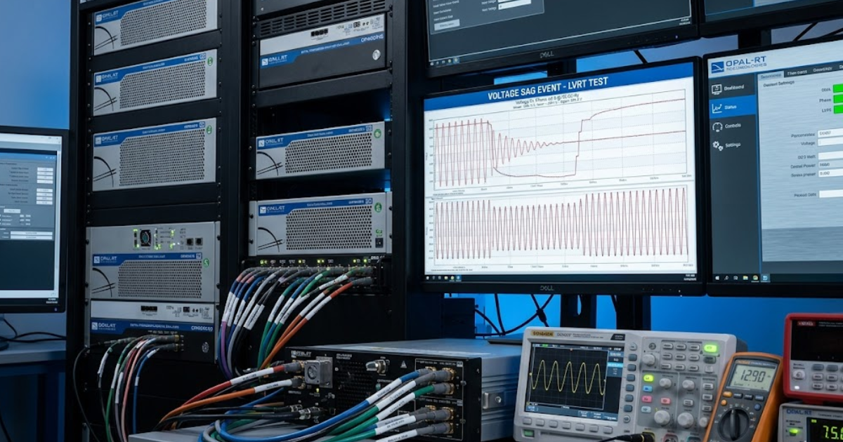
Labs often build the bench around a programmable grid source, precise measurement channels, and a controllable local load for anti-islanding work. A solid setup also includes automation for repeatable sequences. Waveform capture needs enough resolution to verify trip and ride-through timing. Teams that need closed-loop studies often use a real-time simulator such as OPAL-RT to coordinate feeder models, disturbance scripts, and controller interfaces.
- A grid source must hold programmed voltage and frequency during fast transitions.
- Measurement channels must capture waveform timing with traceable accuracy.
- Load control must support tuned islanding conditions near power balance.
- Automation must repeat test scripts without manual timing drift.
- Data logging must link waveforms to settings and firmware records.
Bench quality shows up at the edges. A poorly synchronized trigger can make a compliant inverter look late on trip timing. An unstable grid source can make a non-compliant unit appear to pass ride-through. You want a setup that produces the same answer after a firmware update and during a utility witness test.
Ride through testing depends on precise timing windows
Ride-through testing proves that a DER stays online for required disturbance windows and exits only when a condition crosses the standard boundary. Timing is the key variable. Amplitude alone will not answer the compliance question. You need waveforms that show exactly when the event began, how the DER responded, and when normal operation resumed.
Solar photovoltaic systems supplied 5.4% of global electricity in 2023, so ride-through settings now affect bulk grid performance as well as feeder stability. A typical test applies a defined voltage sag for a specified duration, then checks that the inverter remains connected through the required region. Another sequence pushes frequency above or below nominal. The recorder must show that trip timing occurs only when the programmed boundary is exceeded.
You should pay close attention to event markers, clock alignment, and sampling rate. Small timing errors create big compliance disputes because ride-through windows are often narrow. If your records can’t show when the abnormal condition started and when the device output changed, the utility reviewer will treat the result as incomplete. A clean screen capture will not settle that question.
Anti-islanding validation hinges on worst-case load matching
Anti-islanding validation works only when you test the DER near the condition that makes island detection hardest. That condition is close load matching. The local load consumes almost the same active and reactive power that the DER supplies. When the utility source is removed, voltage and frequency can stay deceptively stable for a short period.
A common setup uses a tuned load bank adjusted until power flow at the point of connection is near zero. Once the utility source is opened, the inverter should detect the island and stop energizing the circuit within the required time. If the load is badly mismatched, detection becomes easy. The test then says little about true anti-islanding performance.
This is where many teams lose credibility. They run islanding tests with convenient load values and collect fast trip times. Utility reviewers know that easy cases are not the compliance case. You need evidence from the difficult operating point, along with clear records of load tuning, switching sequence, and trip timing.
Utility interconnection approval still requires site-specific verification
Utility approval still requires site-specific verification because a compliant DER product enters a feeder with local protection, grounding, and operating rules. Product evidence answers only part of the question. The utility must still verify applied settings and field behaviour. Interconnection approval will hinge on that final alignment.
A rooftop solar project with a certified inverter can still stall if the active voltage and frequency settings do not match the utility’s required profile. Another project can pass lab testing yet fail commissioning because transfer-trip logic or relay coordination was wired incorrectly. Site verification catches those issues before the feeder sees unintended tripping, nuisance alarms, or sustained energization after a switching event.
You should expect utilities to review one-line diagrams, commissioning steps, and settings files with the same care they apply to laboratory evidence. That doesn’t duplicate type testing. It confirms that the approved device, the installed firmware, and the feeder assumptions all point to the same behaviour. The check happens before the breaker closes.
“Good interconnection results come from controlled execution and a test record that stays tied to the approved device configuration.”
Most failed interconnection programs break at settings control
Most failed interconnection programs break at settings control because tested behaviour means little if the fielded device runs different values. Compliance depends on configuration discipline. Firmware, parameter sets, and approval documents must stay linked. When that chain breaks, even a strong test campaign won’t protect the project.
A familiar failure pattern starts after lab approval. Someone updates firmware to fix a minor issue, reloads default protection values, or copies a settings file from another utility territory. The hardware is still the same, yet the approved behaviour is gone. That drift causes last-minute witness test failures and delays that tighter release control and configuration checks would have prevented.
The teams that handle IEEE 1547 well treat testing as one part of a controlled engineering process. They keep settings traceable, bench scripts repeatable, and commissioning records tied to the exact device image in service. That practical discipline is also why engineers use OPAL-RT in validation workflows that need repeatable closed-loop evidence. Good interconnection results come from controlled execution and a test record that stays tied to the approved device configuration.
Real-time solutions across every sector
Explore how OPAL-RT is transforming the world’s most advanced sectors.

Microgrid
05 / 20 / 2026
Grid forming vs grid following inverters and why the difference matters for protection engineers
This guide explains how grid forming and grid following inverters differ in source behaviour, fault response, frequency support, testing, and relay coordination.

Power Systems
05 / 19 / 2026
IEC 61850 GOOSE messaging and how to test it for substation automation projects
A practical guide to IEC 61850 GOOSE messaging, latency targets, interoperability checks, test tools, and the separate role of DNP3 in substation automation.

Microgrid, Energy
05 / 18 / 2026
Battery energy storage system testing that grid operators trust
This piece explains how utilities validate a battery energy storage system through acceptance criteria, closed-loop testing, commissioning, protection checks, duration tests, and traceable evidence.