Flexible PHIL architectures that adapt to evolving power system requirements
Power Systems
04 / 24 / 2026

Key Takeaways
- Flexible PHIL comes from stable timing paths and replaceable interface modules, not from configurable hardware alone.
- Latency budgets and interface contracts set the true limits of modularity in flexible power systems.
- Test benches stay useful longer when teams separate compute, power interface, measurement, and protection logic from the start.
Flexible PHIL works when you keep the timing path fixed and swap the parts around it.
That approach matters because test benches now need to cover inverter control, storage, grid support, protection logic, and fault cases without a rebuild each time. Renewables accounted for 86% of new power capacity added in 2023, which means validation work keeps shifting across converter types and grid conditions. Teams that treat flexibility as an architectural rule, instead of a rack filled with configurable hardware, spend less time rewiring and more time validating behaviour. You get a bench that stays trustworthy as requirements move.
A flexible PHIL architecture uses stable cores with replaceable modules
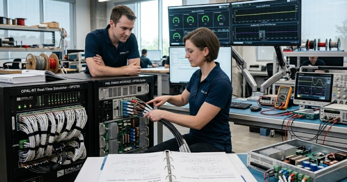
A flexible PHIL architecture keeps the critical simulation path stable and makes the rest of the bench replaceable. The simulator timing, interface contracts, and protection boundaries stay fixed. Power amplifiers, I/O cards, devices under test, and signal conditioning can be swapped without rewriting the full setup.
A microgrid lab shows the difference clearly. You might start with a battery inverter tied to a 480 V feeder model, then shift to a converter tied to an 800 V dc link. If the solver partition, interface model, and safety interlocks stay constant, the team only replaces the electrical interface pieces that actually changed. That is what flexible PHIL architecture means in practice.
You should treat the stable core as a contract. Once timing and interface rules are trusted, every replacement becomes easier to assess. That is also why a flexible setup isn’t the same as a loose collection of modular hardware. Modules help, but discipline around what stays fixed is what makes the system usable.
“A flexible PHIL architecture keeps the critical simulation path stable and makes the rest of the bench replaceable.”
Modularity matters most when power system flexibility sets requirements
Modularity matters when power system flexibility forces frequent shifts in converter rating, control mode, or grid condition. A lab that tests grid following control this month and grid forming control next month needs reusable blocks with clear boundaries. A bench built from scratch for each task will slow your programme.
Battery storage in the power sector grew by more than 130% in 2023. That growth shows why flexible power systems now mix inverter, storage, and protection functions in one validation stream. A team might begin with active power control, then move to black start support, and then test fault ride through without touching the main solver layout.
You’ll get the most value from modularity when it follows requirement volatility. Put effort into the parts that change most often, such as power stage rating, grid impedance profile, and controller I/O mapping. Leave stable items alone. That ordering keeps complexity contained and stops small test plan changes from spilling into a full bench rebuild.
Test bench design should separate interfaces from compute resources
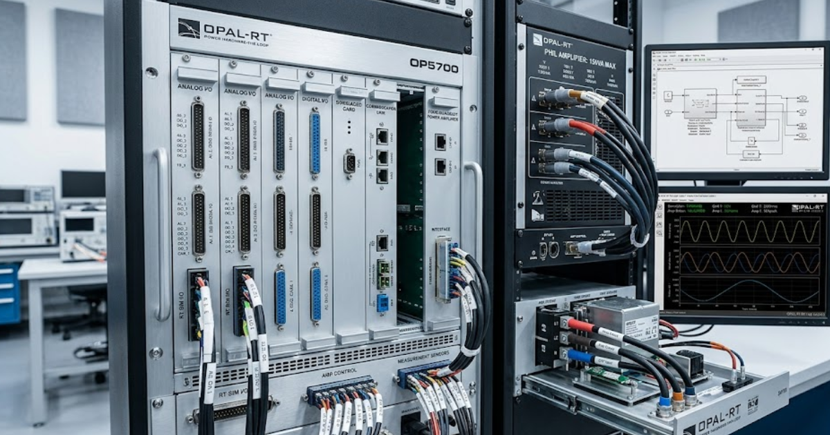
Test bench design works better when compute, power interface, and measurement layers stay separate. You should be able to add processor capacity, replace an amplifier, or change sensor ranges without touching the model partition or the automation scripts. That separation is what makes an adaptable test bench design hold up over time.
A team using OPAL-RT hardware can keep its solver target and I/O contracts intact while swapping a regenerative amplifier for a linear unit to test a different converter class. The compute side still runs the same model boundaries and timing plan. Only the electrical coupling layer changes, so test automation remains intact and previous results stay easier to compare.
This separation also helps during maintenance. If a measurement card fails, you won’t need to reopen the full model just to restore a channel. You replace the card, reload the mapping layer, and verify scaling against a stored interface spec. When compute and interface roles blur, every hardware change turns into a software problem too.
Latency budgets decide which hardware can move freely
Latency budgets decide what can move because PHIL stability depends on delay more than rack convenience. Once round trip delay crosses what the interface algorithm can tolerate, a modular bench stops behaving like one system and starts acting like loosely connected parts. That limit sets the true boundary of your flexibility.
A motor drive controller can often tolerate a different operator station or logging server with no timing penalty, while a power amplifier swap can upset the loop at once. The practical test is simple. If the change touches the feedback path between model and hardware, you need a delay and bandwidth check before you call it modular.
| Bench change | What should stay fixed | Why the check matters |
|---|---|---|
| Moving signal conditioning farther from the simulator | Keep cable delay, shielding, and scaling rules documented before the layout shift | Small placement changes can alter loop timing and measured noise enough to affect stability |
| Replacing a linear amplifier with a switching amplifier | Keep the same interface model only after filter delay and bandwidth are rechecked | The electrical rating can match while the loop response no longer matches your assumptions |
| Adding a network hop between controller and simulator | Keep deterministic latency and jitter within a measured budget rather than an assumed one | Convenient network placement can break hard timing limits even when packets still arrive |
| Moving operator screens to a separate workstation | Keep the user interface outside the timing path and away from control loop execution | Human facing tools rarely need hard timing, so this change usually stays safe and cheap |
| Shifting to a new device voltage range with the same firmware | Keep protection thresholds and sensor scaling under version control as a formal contract | Electrical range changes often create software mismatches that look like hardware faults |
Flexible power supplies solve only one layer of PHIL
Flexible configurable power supplies help with voltage range, current limit, and connector changes, but they do not make a PHIL setup flexible on their own. A bench still needs stable timing, known interface models, and repeatable protection logic across all test states. Power hardware is only one layer of the problem.
A flexible power outlet system can let you move from a 48 V controller bench to a 400 V auxiliary supply test with less rewiring. That saves setup time and reduces operator error. Yet the same bench will still fail if amplifier delay, measurement scaling, or fault handling rules were tuned only for the first use case.
You should see power supplies as support hardware, not as the architectural answer. Teams often spend heavily on rack flexibility and then leave signal paths, model assumptions, and safety states undocumented. That imbalance creates a bench that looks adaptable from the outside but still breaks when the PHIL loop conditions change.
Reusable interface abstraction keeps modular simulation systems practical
Reusable interface abstraction keeps modular simulation systems practical because it separates electrical meaning from specific hardware channels. Your model should speak in named signals, scaling rules, and timing contracts first. The actual card slot, connector, and protocol mapping should sit one layer lower, where you can replace them without rewriting the logic.
A feeder model might publish voltage reference, breaker state, current feedback, and fault flags through a common interface layer. One lab can bind those signals to analogue I/O, while another maps them to a digital controller link. The simulation logic stays the same because the interface contract remains the same, even though the physical bench differs.
This is the point that many modular simulation systems explained poorly in vendor material tend to miss. Abstraction is not paperwork for its own sake. It is what lets you reuse test scripts, compare results across benches, and keep configuration control when teams change hardware. If the abstraction is weak, modular hardware won’t stay modular for long.
Common PHIL failures start with hidden coupling points
Most PHIL failures come from hidden coupling points such as shared clocks, undocumented scaling, or protection logic buried in scripts. The bench looks modular until one small change breaks repeatability. You avoid that trap when every coupling point is treated as an explicit interface that can be checked on its own.
These weak spots show up in the same places again and again:
- A current sensor range changes and the model scaling stays untouched.
- A protection trip lives inside a local script instead of the bench specification.
- A network switch adds jitter that nobody measured after installation.
- A power amplifier filter changes loop response after routine service.
- A device reset sequence depends on operator timing instead of automation.
Each item looks small when viewed alone, which is why teams miss them. The cost appears later, when a test passes on Tuesday and fails on Friday with no clear reason. Hidden coupling points also make knowledge transfer harder. If you want repeatable results, write these links down, version them, and test them like any other bench component.
“Good PHIL architecture will feel boring in the best way.”
Architecture choices should match the next validation step
The right architecture matches the next validation step by preserving what has already been trusted and replacing only what the new test objective truly needs. You should select modules against the next bench question, not against a wish list for every possible lab use. That keeps flexibility practical and controlled.
Good PHIL architecture will feel boring in the best way. When a team moves from controller tuning to grid compliance checks, or from converter testing to plant-level studies, the bench shouldn’t need a heroic rewrite. OPAL-RT fits naturally into this kind of discipline because execution stays centred on tight timing, open interfaces, and controlled hardware substitution.
You don’t need a bench that tries to do everything at once. You need one that preserves trust as scope shifts step by step. Stable cores, measured latency, clean abstraction, and explicit coupling rules will give you that result. Flexible PHIL is less about owning more hardware and more about making careful architectural choices that keep working.
Real-time solutions across every sector
Explore how OPAL-RT is transforming the world’s most advanced sectors.

Power Electronics
07 / 22 / 2026
Testing converter controls safely before connecting hardware
This page explains how fault injection, closed-loop plant models, and recovery checks help validate converter controls before hardware connection.

Power Systems
07 / 21 / 2026
Low voltage ride through testing for grid connected inverters
A practical guide to LVRT test methods, voltage sag profile fidelity, protection checks, and pre-connection verification for grid-connected inverters.

Power Electronics
07 / 20 / 2026
4 Factors when choosing between IGBT SiC and GaN devices
A guide to choosing IGBT, SiC, or GaN devices using switching frequency, voltage class, gate-drive work, thermal cost, and simulation checks.