Hybrid CPU and FPGA workflows for complex power electronics models
Industry applications
03 / 10 / 2026
Key Takeaways
- Hybrid CPU and FPGA simulation works best when partitioning follows timing and coupling constraints, not the visual layout of the model.
- FPGA should carry the switching-heavy sections that need deterministic execution, while CPU should carry wider electrical networks that remain accurate at larger time steps.
- Reliable HIL results depend on disciplined interface timing, limited boundary signals, and staged validation from open loop to closed loop.
Hybrid CPU and FPGA simulation is the practical way to run complex power electronics models in real time once switching detail, machine models, and large network equations stop fitting inside one processing path. The right split is not about putting “fast” work on one device and “slow” work on another in a simplistic way. It is about assigning each part of the model to the resource that can solve it with stable timing, acceptable latency, and enough fidelity to keep your test results useful. Data centres accounted for 1.5% of global electricity demand in 2024, and that share is set to rise to about 3% by 2030, which points to a wider grid and industrial base built around converter-heavy systems that need better validation workflows.
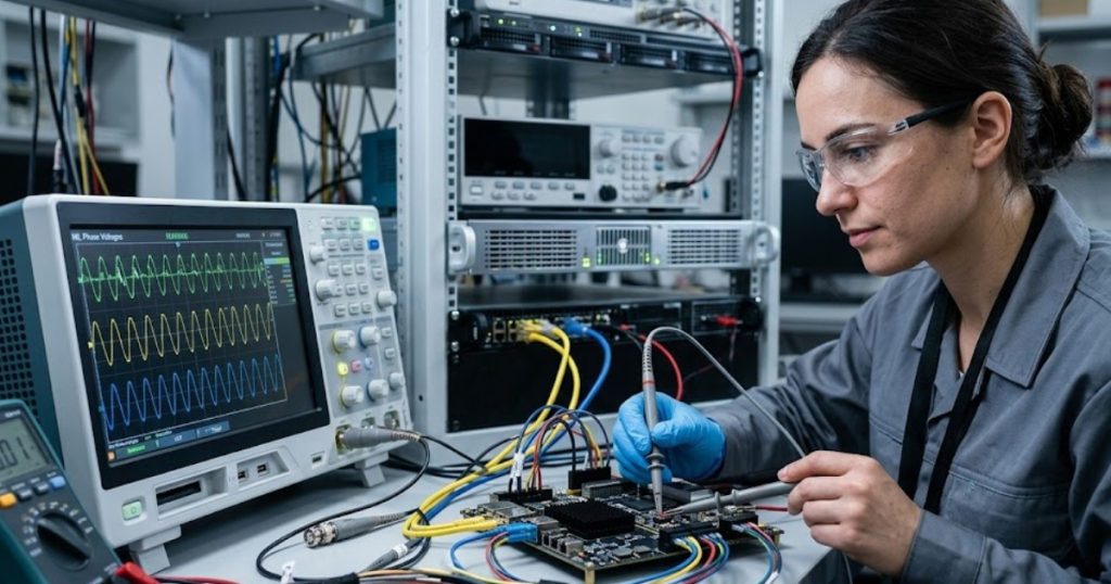
A medium-voltage drive development program recently highlighted this challenge. A cascaded converter model included dozens of switching devices, motor models, sensors, and transformer coupling. Running the entire model on a single processor caused missed real-time deadlines, forcing the team to split the simulation across CPU and FPGA resources.
Complex power electronics models exceed the limits of single-processor simulation
Single processor real-time simulation fails when electrical switching behaviour, machine models, sensors, and large electrical networks must all execute within the same fixed timestep.
Power electronics systems often combine components that operate at very different dynamic speeds. Switching devices change states within microseconds or faster. Machine dynamics unfold over milliseconds. Grid behaviour evolves over longer electrical cycles. When a single processor attempts to solve every subsystem simultaneously, the solver must adopt a timestep small enough to capture switching detail. That requirement quickly pushes computational demand beyond what the processor can sustain in real time.
Motor drive validation provides a practical illustration. A modern drive model may include an inverter stage, current control loops, machine electromagnetic behaviour, encoder signals, and load dynamics. If the switching network requires sub-microsecond resolution, the entire system must follow that timing constraint. The result is excessive computational load and missed execution deadlines.
Hybrid execution removes that bottleneck. Instead of forcing one processor to solve the entire system at the smallest timestep, engineers assign different subsystems to hardware resources suited to their computational behaviour.
Hybrid CPU and FPGA real-time simulation architectures explained
“Hybrid CPU and FPGA simulation is the practical way to run complex power electronics models in real time once switching detail, machine models, and large network equations stop fitting inside one processing path.”
Hybrid simulation divides a model into execution domains that operate at different numerical speeds while remaining synchronized in real time.
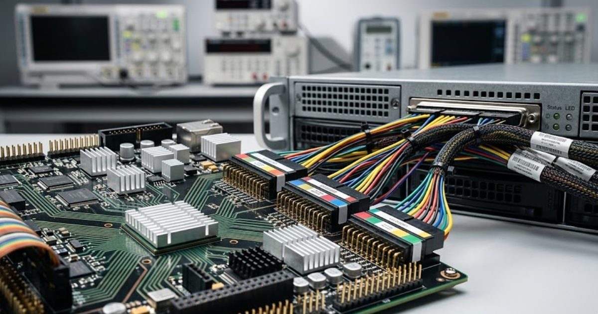
The FPGA portion executes tasks that require extremely small timesteps and deterministic timing. Switching devices, PWM logic, protection mechanisms, and sensor interfaces belong in this domain because they depend on predictable cycle-level behaviour. The CPU portion handles electrical networks, machine dynamics, supervisory logic, and monitoring tasks that tolerate larger timesteps.
Consider a grid-connected inverter validation bench. The switching stage and current measurement pipeline run on FPGA hardware, so the model can reproduce gate transitions and current ripple accurately. Meanwhile, the grid equivalent, transformer model, and supervisory logic run on the CPU. These components still interact with the switching system but do not require nanosecond resolution.
Communication links synchronize both domains so they exchange electrical quantities such as voltage, current, and position at known intervals. The result is a single plant model executing across two processing environments.
Practical principles engineers use to partition models between CPU and FPGA
Good partitioning follows three questions. Which states require the smallest time step, which states can tolerate aggregation, and which interfaces can cross the boundary without corrupting the test.
A converter-rich drive provides a clear example. Gate-level switching events, dead-time effects, and current reconstruction belong near the smallest time step because small errors there will distort the rest of the system. A front-end rectifier with lower switching demands often tolerates execution at tens of microseconds, especially when its purpose is to reproduce bus behaviour rather than every sub-cycle detail.
You also need to group strongly coupled states. A transformer secondary feeding many rectifier paths should not be split at every electrical node just because the diagram looks modular. Partition boundaries should sit where physical interaction is slower, weaker, or already measured as an interface quantity such as voltages, currents, position, or fault flags.
| Partition checkpoint | What the choice means |
| Smallest required time step | Put the section with the tightest timing on the resource that will hold deadline margin under full load. |
| Electrical coupling strength | Keep tightly linked switching and network states on the same side when cross-boundary delay will distort currents or voltages. |
| Interface variable quality | Exchange measured quantities such as phase currents, bus voltage, and rotor position instead of internal solver states. |
| Cost of extra detail | Keep high detail only where it changes control, protection, or power stage results in a meaningful way. |
| Debug visibility | Choose a split that still lets you trace faults to one domain without rebuilding the full model each time. |
Assigning high-frequency switching and converter dynamics to FPGA execution
FPGA execution is the right home for the model parts that need deterministic timing, parallel switching logic, and solver steps that are far smaller than a CPU can hold under real-time load.
A converter with many semiconductor devices, dead-time logic, PWM updates, and fault interlocks is the obvious example. The attached material notes that FPGA-based power electronics tooling can solve switching models at very small time steps and support high switching frequencies, which is exactly what makes it useful for inverter sections, fast protection checks, and encoder or resolver feedback paths.
This matters because the control system often reacts to details that look minor on a schematic. A delayed gate transition, a brief overcurrent spike, or an encoder edge arriving one sample late can alter torque response and trip behaviour. Those are not cosmetic effects. They determine if your controller will survive first power-up.
You should resist the urge to place every power stage on FPGA. FPGA capacity is finite, debugging is more structured, and some subsystems gain very little from nanosecond-scale execution.
Running slower system components and large networks on CPU solvers
CPU solvers are better suited for subsystems that require broader model scope but not extremely small timesteps. Large electrical networks often contain transformers, transmission lines, loads, and machines interacting across longer electrical timescales. Solving these networks efficiently requires flexible numerical methods and the ability to partition equations across multiple processor cores. CPU-based electromagnetic transient solvers perform this task well.
A renewable energy plant model demonstrates the approach. The inverter switching stage runs on FPGA hardware, but the surrounding electrical network contains transformers, cable models, protection devices, and grid equivalents. Those components evolve at slower rates and can be solved with larger timesteps without losing accuracy.
Keeping these subsystems on CPU hardware reduces FPGA resource usage while preserving fidelity for the overall electrical system. Engineers gain a broader system view without forcing high-speed execution on every part of the model.
Synchronization and communication requirements in hybrid real time models
Hybrid models work only when synchronisation, data exchange, and I/O timing are treated as part of the plant model rather than as background plumbing.
Consider a grid inverter controller operating at a fixed control frequency. The controller expects updated phase currents at each cycle. If the FPGA model calculates currents faster than the CPU can transfer them, the controller receives outdated data and reacts incorrectly. Engineers prevent this issue by synchronizing solver timesteps and aligning communication intervals with control sampling rates.
The practical checks are straightforward:
- Match interface sample rates to the control loop, not just the solver loop.
- Keep boundary signals physically meaningful and limited in number.
- Budget latency for transport, scaling, and I/O conversion.
- Verify synchronisation under fault cases, not only steady operation.
- Log both sides of the boundary so timing errors are visible.
Teams that skip these checks often spend days tuning controllers to fix a communications problem.
Common partitioning mistakes that break real-time simulation performance
Most partitioning failures come from poor boundaries, not weak processors.
A common mistake is splitting tightly coupled electrical states because the model hierarchy makes the cut look tidy. Another is pushing full switching detail onto FPGA while leaving dependent measurement and protection logic on CPU, which creates hidden latency in the control path.
Another frequent error is assuming a successful open-loop run proves the partition is correct. Closed-loop HIL will expose timing faults that steady-state offline simulation never shows. Sensor quantization, fault latching, controller resets, and startup sequencing are often where the model breaks. Teams also over-partition for scalability and end up spending more time managing boundaries than solving the engineering problem.
“A disciplined split stays simple.”
Fewer boundaries, cleaner signal exchange, and clear timing ownership will produce more reliable results than a complicated architecture that looks efficient on paper.
Hybrid simulation workflows that support scalable hardware-in-the-loop validation
Scalable HIL validation depends on disciplined model preparation, careful partitioning, and staged testing before controller integration.
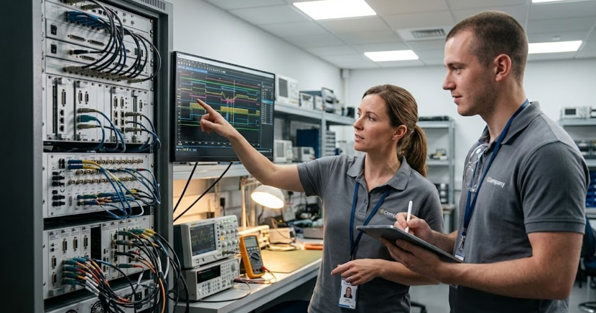
Engineering teams typically begin with offline modelling to validate numerical behaviour. Once the model structure stabilizes, switching-intensive components move to FPGA execution while broader electrical networks remain on the CPU. Open-loop tests verify timing margins, signal scaling, and interface synchronization. Only after those checks does the controller connect to the simulation.
A medium-voltage drive development workflow followed this structure when engineers validated control algorithms using hybrid execution. High-speed converter switching ran on FPGA hardware while slower electrical subsystems executed on the CPU, allowing the team to test protection behaviour and machine response safely before energizing physical equipment.
Platforms developed by OPAL-RT support this type of workflow by providing synchronized CPU and FPGA execution within a unified real-time framework. When partitioning rules are applied consistently, hybrid simulation becomes a dependable engineering tool rather than a fragile prototype model.
Real-time solutions across every sector
Explore how OPAL-RT is transforming the world’s most advanced sectors.

Industry applications, Simulation
03 / 31 / 2026
Managing high-frequency switching in real-time EMT simulation
Precision in testing complex power systems is essential to avoid failures, accelerate innovation, and integrate new technologies safely.

Simulation
03 / 30 / 2026
Understanding timestep requirements for modern power converters
Practical criteria for selecting EMT and real time simulation timesteps for power converters, covering switching resolution, control and PWM timing alignment, multirate approaches, and verification checks.

Energy, Industry applications, Simulation
03 / 29 / 2026
Validating data center energy management systems using real-time HIL
This piece explains how AI workload variability affects data centre power stability and how closed-loop HIL testing helps validate EMS control behaviour under site and grid stress.
EXata CPS has been specifically designed for real-time performance to allow studies of cyberattacks on power systems through the Communication Network layer of any size and connecting to any number of equipment for HIL and PHIL simulations. This is a discrete event simulation toolkit that considers all the inherent physics-based properties that will affect how the network (either wired or wireless) behaves.