Key Takeaways
- Megawatt charging is a controls problem first, because cable cooling, power module sharing and grid limits all interact inside a single truck session.
- Grid connection size follows clustered truck arrivals, so storage and power sharing need the same scrutiny as the charger itself.
- Controller and power hardware-in-the-loop testing expose fault behaviour before energization, when a fix costs a model change instead of a connector.
Megawatt charging system validation succeeds when the charger controls are proven against realistic truck and grid conditions before the site is energized.
Electric truck sales passed 90,000 units globally in 2024 after growing almost 80% in one year, and long-haul fleets need those trucks refilled inside a driver break. That requirement pushes a single dispenser past 1 MW, where cable heating, coolant flow and feeder capacity all become design limits at once. You can’t learn how those limits interact on a finished site, because every mistake there costs a transformer outage or a damaged connector.
The stronger approach treats megawatt charging as a controls problem first. Power stages, cooling loops and grid interfaces behave predictably once their controllers have been exercised against hundreds of charge sessions, weak feeders and fault cases. Real-time simulation and hardware-in-the-loop testing give you that exposure months before civil works finish. Teams that validate early arrive at commissioning with their hardest questions already answered.
What the megawatt charging system is designed to deliver
The megawatt charging system, usually shortened to MCS, is a direct current charging standard built for heavy duty trucks, buses and other large battery vehicles. It defines a single connector, a liquid cooled cable and a communication link sized to move multiple megawatts into one battery pack during a short stop.
Consider a long-haul tractor that needs 400 kWh returned during a 30-minute rest stop. That works out to an average of 800 kW across the whole session, and the peak sits higher because charging power tapers as the pack fills. A passenger car charger rated for 350 kW would need more than an hour to do the same job. The truck would lose a delivery slot.
The design target is a time budget set by driver hours rules and freight schedules. Everything else in the standard follows from that budget, including the higher voltage ceiling and the larger inlet.
How MCS charging works from grid connection to truck inlet
MCS charging works by converting medium voltage grid power into controlled direct current, then delivering it through a liquid cooled cable while the charger and truck exchange limits many times per second. The truck’s battery management system requests current, and the charger follows that request within its own thermal and electrical limits.
A typical site steps medium voltage down through a transformer, rectifies it in a central power cabinet and feeds isolated direct current converters that serve each dispenser. Once the connector locks, the two sides run insulation checks, precharge the cable to match pack voltage and ramp current in stages. Temperature sensors in the contacts report continuously, so the charger will cut power the moment a pin runs hot. Each step is a control handshake with timing limits that only surface as faults when something upstream responds slowly.
MCS compared with CCS for heavy duty vehicles
The main difference between MCS and CCS is the current each connector can carry. CCS, the combined charging system used by passenger cars, tops out at a few hundred kilowatts with liquid cooled cables, while MCS is specified for several megawatts through larger contacts and a higher voltage range.
A research consortium working on truck charging recently demonstrated a charging current of 3,000 amperes, the upper limit of the standard, which also allows up to 1,250 volts. Multiply those ceilings and you get 3.75 MW, roughly 10 times what a high-power car charger delivers.
Current is the hard part. Resistive heating in a conductor rises with the square of current, so a cable carrying 3,000 amperes produces 36 times the heat of the same cable at 500 amperes. That’s why coolant flow, contact temperature and derating logic move from secondary features to primary control loops.
| Design question | CCS on a truck | MCS on a truck |
| How much power reaches the pack | A few hundred kilowatts per inlet | More than 1 MW per inlet, with headroom to 3.75 MW |
| How long a long-haul stop takes | Longer than a mandated rest stop | Short enough to fit inside the rest stop |
| What limits the cable | Cable weight and contact heating at moderate current | Coolant flow and contact temperature at very high current |
| How the site connects to the grid | Often a low voltage service | Usually a dedicated medium voltage connection |
| Where it fits best | Depots with overnight dwell time | Freight corridors and high throughput hubs |
Trucks with CCS inlets will keep using depot chargers overnight. MCS earns its cost on corridors where a stop has to be short.
What megawatt power changes inside the charger power stages
Megawatt power changes the charger from a single converter into a coordinated group of power modules. Dozens of converter modules share current on a common direct current bus, and their controllers must balance load, limit ripple and ride through grid disturbances without tripping the session a truck driver is waiting on.
Picture a 1.2 MW dispenser built from 20 modules rated at 60 kW each. If one module drops out mid-session, the remaining 19 have to absorb its share within milliseconds, or the truck sees a current step and aborts.
Silicon carbide switches, medium voltage front ends and solid state transformers all appear in megawatt designs because they shrink magnetics and cut losses. They also raise switching speeds, which shortens the time a controller has to detect a fault. You’re trading copper and steel for control bandwidth. That trade only pays off when the firmware has been tested at the edges.
“You’re trading copper and steel for control bandwidth.”
Why truck duty cycles set the grid connection size
Truck duty cycles set the grid connection size because megawatt sessions arrive in clusters. Freight schedules send several trucks to the same site within the same hour, and the feeder has to supply the overlap of those sessions, which sits far above the site’s average load.
Take a corridor site with 6 dispensers rated at 1 MW each. A daily average load of 1.5 MW hides a shift change that pulls close to 6 MW for 20 minutes. Sizing the transformer for the average starves the trucks, and sizing it for the peak leaves expensive capacity idle most of the day.
Battery storage and power sharing between dispensers close that gap. A buffer battery charges slowly between arrivals and discharges during the cluster, which lets you connect at a lower rating. The site controller then becomes a small microgrid controller, with its own stability questions.
Weak rural feeders add voltage sag and flicker to the list. Utilities will ask for studies that show how the site behaves during faults and fast load ramps before they approve an interconnection.
How megawatt chargers are tested before a site is energized
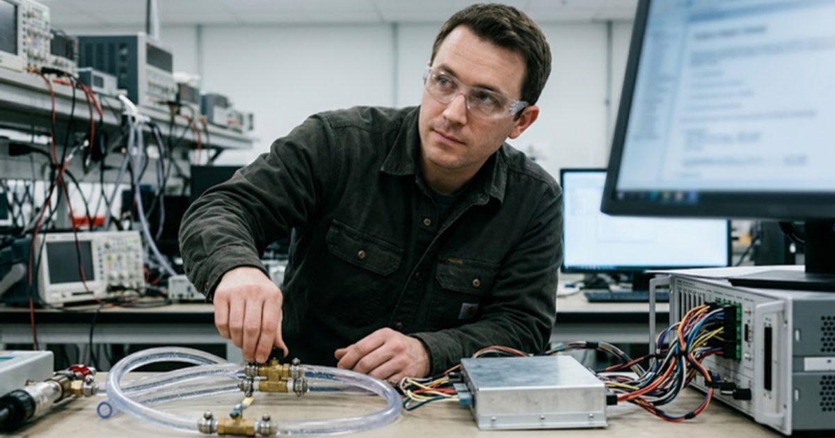
Megawatt chargers are tested in stages that start with simulation and end with full power hardware. Controller hardware-in-the-loop testing connects the real charger controller to a simulated power stage, truck battery and grid, so engineers can run thousands of sessions and faults without any megawatt equipment present.
A real-time simulator solves the grid feeder, the converter modules and the pack model fast enough that the controller can’t tell it from the plant. OPAL-RT real-time grid and battery models are used this way to study MCS charger controls against realistic truck and grid conditions without building a megawatt test site first. Power hardware-in-the-loop then adds an amplifier so a real power module exchanges energy with the simulated feeder. A useful test plan covers the following cases.
- Communication timeouts and malformed messages between truck and charger
- Loss of one power module during a full current session
- Coolant pump failure and contact overtemperature derating
- Grid voltage sags, frequency excursions and feeder faults
- Several trucks arriving at once with a buffer battery near empty
What early validation means for a megawatt charging program
“Early validation means the first truck that plugs in at your site is the thousandth session your controls have seen.”
Megawatt charging programs that prove their control behaviour in simulation spend commissioning time confirming results, and programs that skip that step spend it finding problems at full power.
The physics of megawatt charging is well understood. What separates a smooth site from a troubled one is how many awkward conditions the team rehearsed, from a cold pack on a weak feeder to a cable derating in summer heat. Patient, repeatable testing does more for uptime than any single hardware choice. It’s also far cheaper to repeat a simulated fault than to replace a connector.
OPAL-RT supports that rehearsal with real-time simulation that puts charger controls in front of realistic trucks and grids long before concrete is poured. Start with the control cases that worry you most, model them honestly and let the results shape the site design. Drivers won’t see any of that work. They’ll see a charger that starts on the first attempt.
Automotive
10 / 19 / 2026
Dynamometer testing and motor emulation compared for e-drive programs
A comparison of dynamometer testing and motor emulation for e-drive programs, covering what each method proves, what it costs and how teams sequence both.

Power Electronics
10 / 17 / 2026
How wide bandgap devices push converter power density
Wide bandgap devices raise converter power density through faster switching and smaller passives, and this guide traces that chain from device physics to thermal limits to validation.

Power Electronics
10 / 15 / 2026
Flying capacitor converter simulation for multilevel designs
How a flying capacitor converter balances its capacitor voltages through switching, where that balance breaks, and what a switching-accurate simulation has to capture.