Complete guide to 240V PHIL test benches for modern power system validation
Power Systems
04 / 28 / 2026

Key Takeaways
- A 240 V PHIL bench is defined by closed-loop timing quality, not by voltage rating alone.
- Amplifier behaviour, interface choice, and power separation set the limit on stable and credible validation.
- Platform choice works best when you start with latency targets and treat every source of delay as one budget.
A 240V PHIL bench is only as accurate as its timing, interface, and power separation.
That point matters because a 240 V setup looks simple on paper and still fails once a simulator, amplifier, controller, and protection chain start feeding each other in closed loop. Renewables supplied 30% of global electricity in 2023, so more labs now validate inverter-heavy devices under grid conditions that offline studies cannot reproduce. You need a bench that reproduces voltage, current, delay, and fault behaviour with discipline, or the result will look clean while the hardware is learning the wrong lesson. That is why voltage rating alone won’t tell you if a platform is suitable.
A 240V PHIL test bench links simulation to power hardware
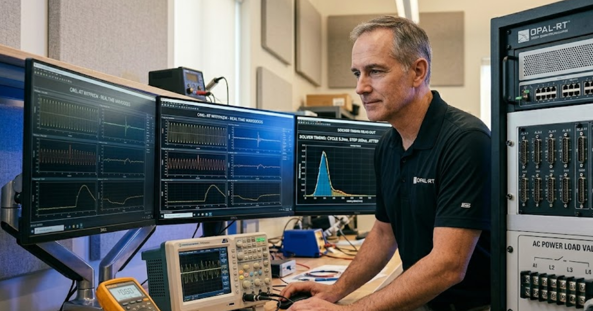
A 240V PHIL test bench connects a real-time power system model to physical hardware through a power amplifier and measurement loop. The simulator computes the electrical system, the amplifier recreates it at 240 V, and the hardware response returns to the model inside each solve step. That closed loop is what makes PHIL different from signal-level testing.
A common setup places a converter, relay, charger, or protection device on the bench while the grid, feeder, or machine stays modelled. A residential inverter test shows the value clearly. You can impose a voltage sag, a phase jump, or a feeder impedance shift and watch the hardware react as if it were tied to a live network. Offline playback can’t supply that feedback path because the power hardware is no longer shaping the simulated system.
The useful distinction is that PHIL validates power behaviour, not only control logic. A standard loopback rig will confirm command handling and state transitions, yet it will miss current distortion, saturation, and DC bus stress that appear once power flows through real hardware. You get earlier evidence of coupled electrical effects, which helps you fix bench issues and hardware issues before site commissioning adds cost and confusion.
“A 240V PHIL test bench connects a real-time power system model to physical hardware through a power amplifier and measurement loop.”
Closed-loop timing sets the limits of usable fidelity
A 240V PHIL system works as a timed loop. The simulator solves the network state, sends voltage or current references to the amplifier, measures the hardware response, and feeds that response into the next solve step. Accuracy depends on total loop delay staying small enough that it doesn’t distort the bandwidth you need to test.
Picture a grid-forming inverter under a step load. The simulator updates feeder voltage, the amplifier applies the new waveform, sensors report current, and the model absorbs that current before the next instant. If any part lags, the bench starts to show phase error, false damping, or oscillation that belongs to the setup instead of the device. Those errors look subtle at first and then dominate the result.
You should treat the loop as one machine, not four separate boxes. Solver step size, analogue I/O delay, filter time, and amplifier response all stack up. That stack decides if your 240 V result reflects hardware behaviour or bench behaviour. Teams that set a full-loop timing budget before wiring the rack usually get stable tests sooner and spend less time chasing effects that move every time the bench configuration changes.
Power amplifier behaviour matters more than headline voltage
Power amplifier choice matters because the amplifier shapes the waveform the hardware actually sees. A unit that can reach 240 V on a nameplate still fails PHIL work if its slew rate, bandwidth, current limit, or output impedance distort the commanded signal inside the closed loop. The voltage rating is only one small part of bench fidelity.
A motor drive bench makes this visible quickly. Regenerative current can push one amplifier into clipping while another stays linear and sinks energy cleanly. The first setup will report harmonic content and fault response that look like control trouble, even though the actual problem sits in amplifier behaviour. Heat rise, recovery time, and response to non-linear loads all matter once the bench starts cycling through severe events.
You should match amplifier type to the device under test and to the intended interface method. Linear amplifiers can give clean small-signal response but waste heat at higher power. Switched amplifiers are efficient and compact but add ripple, filtering delay, and extra control tuning. Headline voltage is only the starting point, and it isn’t a selection method that will protect your test quality on its own.
Interface algorithms decide bench stability before hardware size does
Interface algorithms set the mathematical link between the simulated network and the physical hardware. They decide which variable is imposed, which is measured, and how delay is compensated. Bench stability often depends more on that choice than on rack size, amplifier power, or nominal voltage.
Voltage-source and current-source approaches do not fail in the same way. A stiff voltage source against a converter with strong inner current control can work well, while the same arrangement can destabilize a device with weak damping or a highly inductive connection. Delay compensation and damping terms matter because they shape how aggressively the loop reacts to measured error. Small tuning changes can shift a test from clean to unusable.
You don’t need the most elaborate interface to get valid results. You need the one that matches hardware impedance, expected bandwidth, and fault cases. A modest 240 V source test can stay stable with a simple method if the hardware is passive, while an active front end or grid-support inverter usually needs tighter compensation and more careful tuning. Good interface choice starts with hardware physics, not with feature count.
Bench power architecture must separate control power from test power
Bench power architecture should keep control power separate from test power. The simulator, I/O, sensors, and safety chain need a clean supply that stays stable through trips, while the amplifier and device under test should face deliberate faults, sags, and hard shutdowns without dragging the control side down with them. That split protects both data quality and shutdown order.
That split becomes obvious once you wire a lab around a 240 V power supply and treat every outlet as equal. Control cabinets often use a 100-240 V 50/60 Hz power supply or a class 2 power supply 100-240 V 50/60 Hz for low-power electronics, while the test circuit uses a separate 240 V power supply path sized for amplifier output and fault energy. An uninterruptible power supply 240 V feed belongs on the control side when a sudden drop would corrupt logs or leave contactors half-sequenced. Isolation keeps nuisance trips from turning into lost data and ambiguous shutdown states.
- Keep the simulator and safety relays on a clean protected feed.
- Place amplifier input power on its own breaker and grounding plan.
- Use separate return paths for measurement circuits and power circuits.
- Hold data logging and shutdown logic on backup power.
- Label 100-240 V supplies apart from the 240 V test bus.
Platform fit starts with latency targets for your 240V validation scope
Platform fit starts with latency targets because your validation scope sets the timing budget. A feeder protection study can tolerate more delay than a converter current loop. The best PHIL platform for 240 V testing is the one that meets the required step size, I/O timing, and amplifier coordination for the exact hardware class you’re validating.
Scope is getting broader as inverter-based equipment spreads across utilities, campuses, and industrial sites. Global renewable capacity additions reached nearly 510 GW in 2023. That growth pushes more labs to validate grid-forming functions, anti-islanding, ride-through, and power quality on benches that stay credible under fast electrical transients. A modular setup from OPAL-RT works best when you can assign latency budgets to each path before you assign rack space.
“Good 240 V PHIL work comes from disciplined timing reviews, repeatable interface settings, and clear separation between control power and test power.”
| Selection question | What a good answer sounds like |
| Latency budget | You can state the full round-trip budget and show how solver, I/O, amplifier, and filters fit inside it. |
| Amplifier match | The amplifier stays predictable across current peaks, regeneration, and the fault cases you plan to run. |
| Interface method | The imposed and measured variables match hardware impedance and do not rely on repeated trial tuning. |
| Power architecture | Control electronics stay alive through trips because protected supplies are separate from the 240 V test circuit. |
| Instrumentation path | Sensor scaling, filtering, and timestamping are documented clearly enough that you can repeat the same result later. |
| Expansion path | You can add another converter, relay, or feeder model without rebuilding the whole timing plan. |
Most PHIL failures start with hidden delay mismatch
Most PHIL failures begin with delay mismatch that nobody treated as a single budget. A bench can pass separate component checks and still produce false stability once sensor filtering, software scheduling, amplifier response, and protection logic add more lag than the interface can absorb. That is why hidden delay ruins otherwise good hardware.
A common failure pattern starts after a small bench edit. Someone adds a low-pass filter to clean current noise, another person increases logging, and a firmware update alters amplifier response time. The next test shows ringing during faults, so the hardware team retunes the controller for a problem that lives in the bench. You lose traceability, and the validated settings stop being portable to the next rack or the next project.
Good 240 V PHIL work comes from disciplined timing reviews, repeatable interface settings, and clear separation between control power and test power. Teams that keep those habits tend to trust their results for years, because the bench behaves like a measurement instrument instead of a science project. OPAL-RT fits that kind of practice only when the lab uses the platform with the same timing discipline it expects from the hardware under test.
Real-time solutions across every sector
Explore how OPAL-RT is transforming the world’s most advanced sectors.

Microgrid
05 / 20 / 2026
Grid forming vs grid following inverters and why the difference matters for protection engineers
This guide explains how grid forming and grid following inverters differ in source behaviour, fault response, frequency support, testing, and relay coordination.

Power Systems
05 / 19 / 2026
IEC 61850 GOOSE messaging and how to test it for substation automation projects
A practical guide to IEC 61850 GOOSE messaging, latency targets, interoperability checks, test tools, and the separate role of DNP3 in substation automation.

Microgrid, Energy
05 / 18 / 2026
Battery energy storage system testing that grid operators trust
This piece explains how utilities validate a battery energy storage system through acceptance criteria, closed-loop testing, commissioning, protection checks, duration tests, and traceable evidence.
EXata CPS has been specifically designed for real-time performance to allow studies of cyberattacks on power systems through the Communication Network layer of any size and connecting to any number of equipment for HIL and PHIL simulations. This is a discrete event simulation toolkit that considers all the inherent physics-based properties that will affect how the network (either wired or wireless) behaves.