Key Takeaways
- Power system models and communication network models catch different failure modes, so a utility program that tests them separately carries risk it cannot see.
- Simulation effort pays back fastest on feeders where an upgrade changes fault behaviour or moves a control decision onto a network link.
- A maintained library of tested cases turns validation into a standing capability and shortens every commissioning cycle that follows.
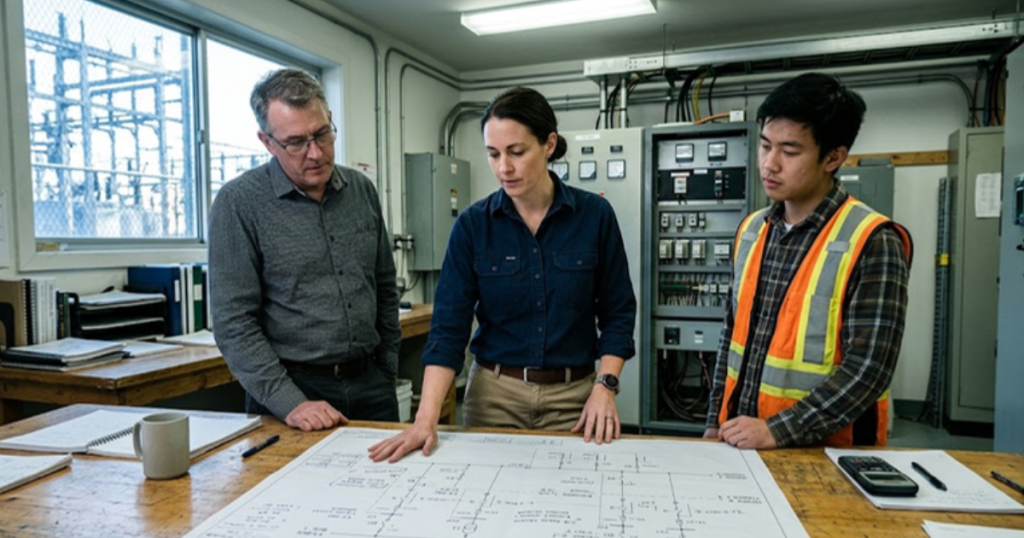
Utility grid modernization programs succeed or fail on how well the power system and the communication network get validated as one system before equipment reaches the field.
Most program plans treat those two layers as separate engineering problems. Planners size feeders, protection schemes and inverter settings in one toolchain, while the telecommunications group specifies latency budgets, radio coverage and cybersecurity controls in another. Neither group owns the interaction, and that’s where pilots stall. US battery storage capacity reached nearly 52 GW in mid 2026 after 8.3 GW came online in six months, and each of those assets answers to a controller that speaks over a network.
Sizing an asset correctly doesn’t help you if the setpoint arrives 400 milliseconds late or lands during a radio outage. Utilities that validate both layers on one clock catch that problem in the lab, where a fix costs an afternoon. Utilities that skip the step catch it at commissioning, or during the first storm season.
What grid modernization simulation actually proves for utility programs
Grid modernization simulation proves that a planned upgrade behaves correctly when power equipment, protection logic and the communication network all run at once. It replaces the assumption that every piece works because it passed its own bench test, and shows the order in which things break when a message arrives late.
A volt/VAR scheme makes the point quickly. Planners specify a loop that reads voltage at three points on a feeder, computes a setpoint at the substation and pushes it to a capacitor bank controller. On paper the loop closes in under a second. Modelled with a full protocol stack and a shared radio link carrying metering traffic, it closes in three seconds at evening peak and the regulator starts hunting. That finding changes the design while it’s still cheap to change.
A pilot that misbehaves in front of customers consumes regulatory goodwill, and rate case commitments are hard to renegotiate once a schedule slips. Smart grid simulation gives you a defensible record of what was tested and under which failure conditions, which is the evidence commission staff will ask for.
Why single layer models miss program level failure modes
Single layer models miss failures that live between layers. A power system study assumes control signals arrive instantly and intact. A network study assumes the physical plant tolerates any delay the link introduces. Both assumptions hold in isolation and fail once the two systems share a timeline.
Fault location, isolation and service restoration schemes show the cost of that blind spot. A restoration sequence that looks correct in a load flow tool will reclose onto a section that hasn’t cleared if the status message from a downstream recloser is queued behind a firmware push. The power model reports a clean restoration and the network model reports acceptable average latency, while the combined case reports a reclose onto a fault.
Program teams tend to discover this through incidents rather than analysis, because incident reports are the only place the two layers get examined side by side. Pulling that examination into the modelling stage costs little. It’s a scoping decision about which test cases get built.
“Both assumptions hold in isolation and fail once the two systems share a timeline.”
How communication network behaviour shapes protection and control results
Network behaviour sets the outer limit on how fast any distributed control scheme can act. Latency, jitter, packet loss and traffic contention all change the effective response time of a protection or coordination scheme, and none of them appear in a conventional power system model.
IEC 61850 GOOSE messaging illustrates the constraint. Bus protection built on GOOSE assumes trip messages land within a few milliseconds over a dedicated substation LAN. Utilities extending that scheme across feeders over a shared cellular link often find background traffic pushes the message past its window at peak hours, so protection reverts to slower local logic and clearing times roughly double. Nothing failed. The scheme ran outside the conditions it was designed for.
Modelling this correctly means running the power solver and a network emulator on one clock, so a delayed packet lands in the power model at the microsecond it would have landed in the field. OPAL-RT builds that pairing by running HYPERSIM for the power layer alongside Exata CPS for the communications layer, which lets a protection engineer and a network engineer read the same event log.
“Network behaviour sets the outer limit on how fast any distributed control scheme can act.”
Where utilities should focus simulation effort first
Focus first on the cases where the upgrade changes fault behaviour or moves a control decision off the device that used to make it. Those two conditions cover most of the failure modes that reach customers, and they’re straightforward to identify from existing planning data.
The volume of interconnection work makes prioritization unavoidable. About 8,200 projects were waiting on transmission interconnection at the end of 2025, representing 1,312 GW of generation plus roughly 749 GW of storage. No utility has the lab hours to model every one of them at full fidelity, so the selection criteria matter more than the tool.
- Feeders where distributed generation output already exceeds minimum daytime load.
- Protection zones moving from local logic to networked tripping.
- Substations served by a single communication path with no second route.
- Control schemes whose setpoints update faster than the network confirms delivery.
- Sites where the upgrade shifts fault current levels for existing relays.
Ranking this way usually produces 15 to 30 feeders out of several hundred, a workload a two person lab can carry.
Comparing offline studies with hardware-in-the-loop validation
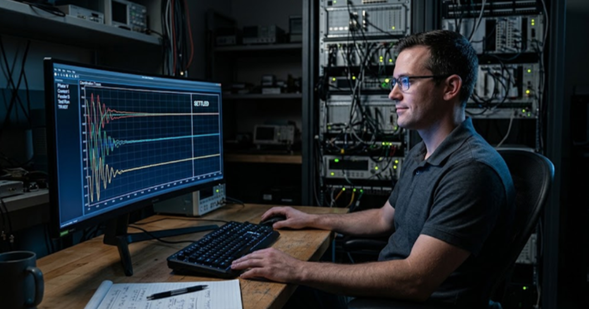
The main difference between offline studies and hardware-in-the-loop validation is what gets tested. An offline study tests your model of the controller. Hardware-in-the-loop tests the controller itself, with its shipped firmware, its actual settings file and its real processing delay.
That distinction decides how much commissioning surprise you’re willing to accept. Settings errors, firmware mismatches and vendor-specific readings of a standard never appear in a model, because the model reflects the specification rather than the product.
| Validation stage | What a program team learns and where it stops short |
| Steady state load flow | Confirms voltages and currents stay inside limits under average conditions, and says nothing about timing. |
| Offline electromagnetic transient study | Captures fast switching and fault behaviour, though the controller is still a model rather than the shipped product. |
| Controller hardware in the loop | Runs the actual relay or inverter controller against a live power model, so setting errors surface before commissioning. |
| Power hardware in the loop | Puts physical equipment on a simulated feeder and exposes thermal limits that signal level testing hides. |
| Coupled power and network simulation | Adds latency, packet loss and traffic contention, showing how a scheme degrades when the link is congested. |
Common mistakes that undermine DER coordination testing
The most expensive mistake in DER coordination testing is validating each resource on its own. Coordination problems are group behaviours. A single inverter riding through a voltage dip is fine. Forty inverters on one feeder, all following the same ride through curve with the same manufacturer timing, produce a collective response no individual test showed.
Aggregation assumptions cause similar trouble. Program teams often model 200 rooftop systems as one equivalent source at the feeder head, which hides the sequencing that makes coordination hard. Voltage rises at the end of the line before it rises at the head, so the units that trip first are the ones the aggregate model never represented. Restoration then happens in an order nobody planned.
Test case libraries age badly too. A coordination case built against an older interconnection standard won’t exercise the ride through and frequency response settings current inverters ship with, and a passing result on a stale case carries false confidence into a design review. Keeping the library current is unglamorous work, and it’s the work that keeps the rest of the program honest.
How disciplined validation shapes utility program outcomes over time
Utilities that get the most out of grid modernization spending are rarely the ones with the largest budgets. They’re the ones that made validation a standing capability instead of a project line item, so every feeder upgrade, every new inverter model and every protection change goes through the same lab before it reaches a customer.
What compounds is the case library. A utility three years into this practice has hundreds of tested scenarios and engineers who can tell you within a day if a proposed change will hold. A utility starting fresh on each project rebuilds that understanding every time and pays for it in commissioning delays. Platforms like OPAL-RT support that accumulation because the same models carry from a desktop study into full hardware-in-the-loop testing.
The judgment worth holding onto is simple. Treat the communication network as part of the power system, test them on one clock, and keep the results where the next engineer can find them. Programs built that way don’t run out of surprises, but they run out of the expensive ones.

Power Systems
10 / 24 / 2026
800 VDC power distribution for AI data centers
An explanation of how 800 VDC power distribution carries power from the grid to AI racks, covering conversion stages, DC fault protection and bus stability.
Automotive
10 / 21 / 2026
Megawatt charging system validation for heavy duty trucks
A practical look at how the megawatt charging system works, how it differs from CCS and how charger controls are tested before a truck site is energized.
Automotive
10 / 19 / 2026
Dynamometer testing and motor emulation compared for e-drive programs
A comparison of dynamometer testing and motor emulation for e-drive programs, covering what each method proves, what it costs and how teams sequence both.