What Is Communication Protocol in PLC? A Technical Guide for Senior Engineers

Communication protocols in PLC systems shape the flow of critical data across industrial operations. They form the structured ruleset that ensures devices speak the same language, resulting in faster production changes and more efficient resource allocation. Engineers rely on these protocols to maintain consistent performance, reduce downtime, and enhance stakeholder alignment. Selecting the right protocol fosters measurable impact, including shortened project timelines and better returns on investment.

Why Communication Protocols Are Central to PLC Systems


Successful PLC systems rest on consistent and secure data exchange across all connected devices. An effective communication protocol in PLC plays a direct role in maintaining accurate measurements, driving precise commands, and detecting anomalies before they escalate. This focus on robust data sharing helps reduce production errors and supports high-level analytics, which often elevates quality standards for end-users.

Engineers appreciate communication protocols in PLC because they streamline customization and future expansions. Scalable protocols allow for phased additions of equipment, which shortens time to market and simplifies upgrades. Many teams also see communication protocols as essential for cost management, since proper configurations can lower integration overhead and reduce the burden on technical staff.

Defining Communication Protocols in PLC Setups


A communication protocol in a PLC setup outlines how controllers, sensors, drives, and related devices exchange data. Everything from the low-level arrangement of bits to how each packet is labeled falls under this set of rules. These protocols address how a device recognizes the start of a message, checks its length, and finalizes the communication.

Protocols also manage error detection and handling. This involves methods for catching corrupted packets or identifying lost data, followed by initiating re-transmission routines to maintain a reliable data flow. Device identification is another critical function of these protocols. Each controller or sensor is assigned a unique address, which prevents conflicts and ensures that data reaches the correct destination within the network.

Security provisions are particularly important in sensitive industries like energy infrastructure and aerospace. Communication protocols frequently incorporate measures designed to prevent unauthorized access and guard against data tampering or interference. PLC systems run best when each layer of communication remains predictable. Manufacturing floors, grid simulation labs, and aerospace test stands benefit significantly from protocols that facilitate fast, accurate data exchanges. This consistent data handling is essential for advanced real-time simulation, where responses measured in microseconds often determine the success of critical projects

Protocol Selection: Impact on Project Outcomes


Communication protocols significantly influence development timelines, resource allocation, and overall system reliability. Carefully chosen standards cut guesswork by ensuring each device interprets data the same way. A strong match between protocol features and project goals often drives:

  1. Fast Commissioning: Standardized messaging reduces the time needed to bring systems online. Engineers can focus on optimizing performance instead of fighting connectivity hurdles.

  2. Better Allocation of Technical Staff: If a protocol is well documented and widely used, teams spend less time on troubleshooting and more time refining advanced control strategies.

  3. Cost Control: Fewer rewrites of communication logic mean fewer unplanned expenses. Teams reassign hours away from patching connectivity issues toward future-focused tasks.

  4. Long-Term Stability: Protocols known for backward compatibility let organizations integrate new hardware or software without forcing entire redesigns.

These benefits resonate across sectors that demand real-time assurance. For instance, automotive engineers fine-tuning advanced driver-assist features need reliable PLC links for brake sensors, electric powertrains, and battery systems. Power systems engineers conducting grid simulations rely on stable data exchange to evaluate load changes or harmonic conditions.

Common Communication Protocols in PLC Systems


Engineers often compare a handful of widely adopted protocols, each with a track record for reliability, speed, or simplicity. The choice usually depends on physical constraints, existing infrastructure, and the specific performance targets of an application. Below are some leading protocols that appear frequently across multiple industries.

1. Modbus

Modbus promises a straightforward way to link PLCs with various field devices. It relies on a master-slave configuration, where a primary controller initiates communication and secondary devices respond. Many engineers rely on it for its simplicity, especially in applications like data monitoring or reading sensor values. Swift adoption often results in fewer barriers when adding new devices or performing updates.

One measurable benefit of Modbus is the ability to scale systems without large modifications to existing infrastructure. This compatibility eases change management concerns by minimizing resource-intensive rewiring or recoding efforts. Another advantage appears in cost-effectiveness, as it operates efficiently on a serial link or TCP/IP connection without specialized hardware. The result is an optimized approach that supports quicker deployment and reduces downtime for maintenance tasks.

2. PROFIBUS

PROFIBUS (Process Field Bus) delivers robust performance tailored for complex process control applications. It features deterministic communication, ensuring devices transmit data at precise intervals. This capability suits situations with strict time constraints, like high-speed assembly lines or advanced manufacturing cells. Smoother integration with distributed I/O modules often translates to improved governance over large-scale operations.

Teams benefit from PROFIBUS because it supports a range of device types while maintaining dependable data throughput. It also enables straightforward diagnostics, which helps detect potential faults early and shortens troubleshooting cycles. Many organizations appreciate its modular structure, which simplifies expansions and upgrades. Faster reconfiguration times often lead to time savings and a measurable impact on overall system productivity.

3. Ethernet/IP

Ethernet/IP applies standard Ethernet technology to industrial communication needs, combining familiarity with robust performance. Its open architecture encourages flexible data exchange between PLCs, controllers, and management systems. High bandwidth and quick response times suit sophisticated use cases, including motion control or distributed manufacturing processes. Teams with existing Ethernet networks typically find it easier to merge this protocol into their infrastructure.

One vital advantage is its alignment with mainstream network equipment, which lowers implementation costs while providing a broad hardware selection. This approach improves scale-up efforts by using standard cabling and networking practices. Another takeaway is the support for advanced analytics, as Ethernet/IP can carry large data packets for remote access or monitoring. This opens new ways to manage assets, resulting in reduced downtime and more efficient resource allocation.

4. DeviceNet

DeviceNet connects PLCs with industrial devices such as sensors, actuators, and motor drives on a single network. It operates on a producer-consumer model, sharing data in a structured way that reduces the load on controllers. This design focuses on simpler wiring, with the power and data signals combined in a single cable to cut material costs and speed up installations. Many technicians value DeviceNet for direct access to device parameters and status information.

Simplified wiring translates into measurable business returns, since installation time and material expenses often decrease. This advantage becomes more pronounced in large-scale facilities where engineers might replace or upgrade devices frequently. DeviceNet also supports intelligent device monitoring, which shortens downtime by spotting hardware faults in real time. The end result is a cost-effective protocol option that helps managers optimize maintenance schedules.

5. CANopen

CANopen builds upon the Controller Area Network (CAN) and focuses on flexible configuration and real-time support. It often appears in applications where devices need to communicate continuously without heavy overhead. This protocol segments communication tasks into different message objects, which can prioritize critical signals over less essential data. Many users appreciate the straightforward device profiles that define how sensors and actuators behave, making configuration more consistent and intuitive.

One notable outcome is that CANopen helps reveal ways to reduce integration complexity and consolidate PLC tasks on a single bus. Reducing complexity often leads to direct cost savings, as fewer hours go toward debugging or fine-tuning multiple networks. Another important benefit involves safer operations in automotive and heavy machinery environments, where short update cycles enhance reliability. The result is a framework that keeps downtime low while allowing for future expansions.

Critical Building Blocks of Protocol Design


Each protocol incorporates layers that govern how devices establish connections, transfer data, and handle errors. Senior engineers who plan expansions or set up HIL simulations need to account for these elements:

  1. Connection and Handshaking: A predefined routine that determines how devices initiate contact and confirm readiness for data exchange. Early-phase clarity ensures minimal confusion during rapid network startups.
  2. Packet Architecture and Formatting: Identical data structures across devices support faster interpretation and reduce message corruption. Structured packets also make partial troubleshooting simpler.
  3. Error Checking and Correction: Methods such as checksums or CRC (Cyclic Redundancy Check) detect transmission faults. Automatic re-transmission routines or error flags reduce data loss in critical processes.
  4. Addressing or Node Identification: Unique addresses eliminate signal collisions. Properly managed ID ranges help the network scale while retaining clarity around which device owns a specific data variable.
  5. Security and Access Controls: Robust protocols often include encryption or authentication methods. Industrial labs with valuable IP or safety concerns need layered security to prevent unauthorized commands or data interception.

Upfront planning in these areas saves future hours spent on troubleshooting. A consistent packet format, for instance, means every new sensor can follow a standardized process to announce its presence. This uniformity keeps expansions from turning into costly reworks and prevents confusion when multiple engineering teams share lab resources.

Trends Shaping PLC Communication Protocols


Development teams see an ongoing push toward open standards, unified data handling, and simplified integration with advanced analytics. Large projects in energy and aerospace often merge legacy PLC hardware with modern solutions, including AI-based processing for real-time anomaly detection or predictive maintenance. Standardized protocols make these hybrid approaches feasible by ensuring data consistency across all devices.

  • Convergence of Operational and IT Networks: Cloud platforms gather real-time plant metrics to guide long-term planning. Protocols that support robust security and standardized data structures are crucial in bridging these two worlds.
  • Wireless and IIoT Integration: Some operations add wireless nodes to gather data from remote or mobile assets. Protocol updates that handle encryption and authentication help maintain reliability in these distributed networks.
  • Stronger Security Measures: Industrial settings emphasize encryption, intrusion detection, and secure device authentication to reduce risks. Communication protocols now frequently incorporate these measures as standard features.
  • AI-Focused Tools: Machine learning solutions need large datasets for accuracy. Protocols offering consistent message formatting ensure data from controllers, sensors, or power inverters is gathered without confusion.

Forward-thinking teams often prioritize protocols with a strong track record, robust documentation, and flexible expansion options. Each of these attributes reduces headaches when next-generation requirements, such as extended HIL tests, multi-physics simulations, or cloud-based HPC, arrive. Many labs see direct cost savings by choosing a protocol that accommodates growth without forcing entire system rewrites.

Aligning Protocol Choices with Real-Time Simulation Goals


Real-time simulation, especially Hardware-in-the-Loop testing, brings engineering prototypes face-to-face with realistic conditions. Systems must process feedback signals with minimal latency and feed accurate data back into physical or virtual components. A suitable protocol stabilizes these transactions, ensuring signals arrive without delay or corruption.

  • Precision: HIL tests replicate events like grid faults or rapid speed changes in an electric motor. Protocols must handle bursts of data without dropping packets.
  • Scalability: Large labs might simulate a microgrid with dozens of connected inverters. Each device node needs a clear addressing scheme so logs remain traceable.
  • Integration with Multiple Toolchains: Real-time platforms frequently link to MATLAB/Simulink, Python scripts, or custom software. Protocols that follow open standards reduce friction when bridging these tools.

At OPAL-RT, real-time digital simulators integrate seamlessly with many PLC communication protocols. Solutions like OP4200 or OP7000 accommodate these standards through modular I/O interfaces, letting engineers consolidate data from high-fidelity power electronics tests and mechanical subsystems on a single unified platform. This level of interoperability helps avoid the pitfalls of proprietary lock-in, making expansions straightforward as research evolves from small bench models to full-scale prototypes.

Strategies for Senior Engineers and Technical Leads


  1. Identify Project-Specific Constraints: High-voltage aerospace tests have different timing demands than automotive battery management setups. Match protocol capabilities (bandwidth, determinism, security) to the real-time challenges of each scenario.
  2. Favor Open Standards: Proprietary solutions can simplify short-term tasks but lock teams out of flexible expansions. Publicly documented protocols with wide vendor support often reduce future headaches.
  3. Confirm Compatibility with Simulation Tools: Many labs incorporate custom modeling or co-simulation. Verify that the protocol aligns with existing toolchains, so communication overhead doesn’t inflate test cycles or break key data links.
  4. Invest in Scalable Hardware Platforms: Choose real-time simulators and PLC equipment that can grow in parallel. Protocol adaptors or modular I/O expansions help keep up with new sensor installations or updated HIL test requirements.
  5. Emphasize Security Early: Once a setup is operational, retrofitting encryption or secure authentication can disrupt data flows. Engineers can avoid extensive rewrites by designing secure communication from the beginning.

How OPAL-RT Supports Communication Protocol Objectives


OPAL-RT has spent decades refining real-time simulation tools that give engineers a wide canvas for integration. Senior simulation specialists in energy, automotive, and aerospace can connect PLCs using Modbus, PROFIBUS, Ethernet/IP, or additional protocols through dedicated interface modules. These solutions handle the heavy lifting of fast data exchange while preserving the nuance required for high-fidelity modeling of power circuits, flight control surfaces, or advanced propulsion systems.

Distinct Benefits for Complex Projects:

  • Ultra-Low Latency: FPGA-accelerated simulation ensures that protocol exchanges happen without bottlenecks, which is essential in situations like motor torque validation or grid fault replication.
  • Modular Architecture: Scalable platforms let teams add protocol modules only when needed. This approach locks in cost savings while leaving room for expansions in energy distribution or automotive sensor arrays.
  • Flexible Toolchain Compatibility: Native support for a range of workflows means real-time data can flow directly from the simulator to analytics dashboards without specialized converters.

Engineers and innovators across multiple fields turn to real-time simulation to shorten development time, minimize risk, and expand what’s possible. At OPAL-RT, we offer decades of expertise and a passion for innovation, delivering open, scalable, and high-performance simulation platforms. From Hardware-in-the-Loop testing to AI-based cloud simulation, teams can design, test, and validate with confidence.

Frequently Asked Questions

It sets the rules for how devices exchange data, which affects speed and reliability. A well-chosen communication protocol in PLC systems can streamline data flow, lower integration hurdles, and increase production efficiency. It also supports real-time monitoring, improving your ability to make quick operational adjustments.


Many teams pick Ethernet/IP for its compatibility with standard networking devices, resulting in easier scaling. Others prefer Modbus TCP due to widespread support and straightforward setup. The best choice depends on performance demands and existing infrastructure, so evaluating project goals remains essential.


They often reduce material expenses by simplifying wiring and reducing installation time. A protocol like DeviceNet merges data and power in one cable, cutting hardware costs. This focus on streamlined networks boosts productivity and can optimize returns over the system lifecycle.


They protect critical data from unauthorized access through encryption and access control. Network segmentation also plays a role in minimizing vulnerabilities across multiple devices. These safeguards help maintain uptime, reduce unexpected costs, and build trust with internal and external stakeholders.


The main difference between these two protocols lies in bandwidth and structure. Ethernet/IP supports higher data rates using standard Ethernet equipment, while Modbus takes a simpler approach that suits legacy systems. Each option can address unique needs, so decisions often hinge on specific performance requirements and existing infrastructure.




Understanding the Differences Between Rapid Control Prototyping vs HIL

Real-time validation marks the difference between guesswork and measurable progress for projects involving advanced control systems. Precise testing methods, such as Rapid Control Prototyping (RCP) and Hardware-in-the-Loop (HIL), help senior engineers reduce technical risk, refine control logic, and confirm hardware performance in a streamlined development cycle.

Senior engineers, principal simulation experts, and R&D managers often work with intricate control systems in energy, aerospace, automotive, and academia. Real-time validation is crucial to streamline project timelines and mitigate risk. Rapid control prototyping (RCP) and hardware-in-the-loop (HIL) testing both address these needs. Each approach accelerates validation, reduces late-stage rework, and boosts confidence in production outcomes. This guide compares RCP and HIL through a technical lens, showing how each method fits specific stages of development.

Why Real-Time Validation Matters


Complex projects demand test methods that accurately replicate operational conditions. Lab managers and lead engineers aim to reduce trial-and-error cycles, enhance reliability, and keep budgets on track. RCP and HIL each respond to these goals:

  • Shorter time to market through repeatable experiments
  • High-fidelity insights that uncover early-stage flaws
  • Efficient iteration to refine designs on a tight schedule
  • Targeted performance metrics that confirm core system capabilities

These methods support engineering teams looking to validate advanced control logic or confirm hardware behavior under stress, all within a safe and precise test environment.

“RCP shortens initial trials by integrating control models with ready-to-use hardware”

Defining Rapid Control Prototyping (RCP)


RCP lets you evaluate new control algorithms in real time on physical hardware before finalizing production designs. This approach brings together prototyping hardware and software modeling tools, allowing quick testing of advanced concepts with minimal risk. Traditional cycles can be expensive and slow, so RCP is a practical way to confirm design choices earlier.

Teams working on motor drives, power converters, or sophisticated automotive controls find RCP especially helpful. Real-time evaluation highlights potential issues with control stability, timing, and response under changing loads. By testing control logic on versatile hardware, adjustments become simpler and more cost-effective.

Practical Advantages of RCP

  • Faster proof-of-concept: Compact testing platforms merge control models with ready-to-use hardware for quick evaluation.
  • Early detection of flaws: Physical interaction pinpoints control vulnerabilities before finalizing designs.
  • Lower technical risk: Iterative feedback loops reduce the likelihood of late-stage redesigns.
  • Better resource allocation: Accurate performance metrics guide planning for materials and engineering hours.
  • Clear stakeholder communication: Live demonstrations reveal how algorithms react under realistic conditions.
  • Simple scalability: Modular setups accommodate feature expansions or new subsystems with minimal disruption.
  • Budget-friendly approach: Early detection of design flaws saves time and cuts costs associated with major hardware overhauls.

RCP streamlines overall development by validating software-based logic in parallel with initial hardware checks. This level of insight supports advanced concepts while keeping teams agile in early project phases.

Defining Hardware-in-the-Loop (HIL) Testing


HIL pairs real hardware with a simulator that reproduces conditions a system faces in actual operation. This configuration uses actual controllers linked to detailed models of plants, sensors, or other subsystems. The result is a reliable way to verify hardware robustness in various stress scenarios, all without risking expensive equipment on physical test tracks or labs.

Many automotive, aerospace, and energy groups rely on HIL to confirm the performance of controllers or prototypes. HIL reveals how physical devices respond to shifting signals, fault conditions, and edge cases that typical software-only simulations might overlook.

Core Benefits of HIL

  • Reduced field testing overhead: Simulated signals cut down on real-world trials that could otherwise be costly or time-consuming.
  • Safety checks for critical systems: High-stress conditions can be replicated in a lab, protecting personnel and equipment.
  • Accurate performance data: Real-time metrics capture how hardware reacts to dynamic inputs and load variations.
  • Enhanced debugging: Engineers can visualize hardware responses to identify exactly where a malfunction may occur.
  • Regulatory compliance: Many industries, including automotive and aerospace, rely on HIL to confirm designs align with required standards.
  • Stakeholder confidence: Tangible evidence of hardware stability fosters trust in final implementations.
  • Straightforward expansion: Combining multiple modules or subsystems into a single test bench is manageable with modular test rigs.

HIL is a prime approach for later project stages, where hardware-based proof is crucial. It ensures physical components can endure the real demands of service, boosting certainty before production.

Comparing RCP and HIL


RCP focuses on fine-tuning algorithms, whereas HIL concentrates on hardware performance in simulated conditions. RCP appears early, helping teams iterate control logic. HIL follows when design teams require verification that physical devices react properly.

Dimension

RCP

HIL

Primary Focus

Validating control logic in real time

Stress-testing hardware with simulated signals

Development

Early to mid-stage control design

Later-stage validation, prior to production

Core Advantage

Rapid iteration on software-based solutions

Comprehensive hardware performance checks

Key Benefit

Prevents costly software rework

Prevents hardware issues and on-site malfunctions

Primary Outcome

Fine-tuned control algorithms

Reliable final device behavior


Some projects need both approaches. Senior engineers commonly apply RCP to refine early control design, then adopt HIL for hardware-specific proof. This layered approach suits systems requiring deep hardware-software alignment.

When to Use RCP vs HIL


RCP is ideal if your main goal is refining innovative control algorithms before investing in final hardware. This scenario often appears in advanced energy setups, robotics, or automotive designs aiming for rapid iteration cycles.

HIL is best when you must confirm hardware integrity under rigorous conditions. Safety-critical projects or multi-sensor integrations—such as flight controls, EV power electronics, or complex power systems, require HIL to validate that physical devices meet stringent performance benchmarks.

Budget, scheduling, and the level of hardware integration needed all influence the choice. Many engineers start with RCP to confirm design concepts, then shift to HIL once a final hardware path is set.

Application Examples Across Industries


Both RCP and HIL are widely used in sectors prioritizing real-time precision. Below are a few examples that show how RCP or HIL can drive project success:

  • Automotive systems: Battery management, engine controllers, and driver-assist modules benefit from quick iterations early on, followed by hardware checks to confirm reliability.
  • Aerospace: Flight controllers and avionics need extensive simulator-driven testing before physical flight trials. RCP refines algorithms, and HIL ensures hardware aligns with strict safety rules.
  • Industrial robotics: Robotic arms rely on responsive control logic for motion, collision protection, and process repeatability. RCP fine-tunes complex algorithms, while HIL verifies hardware in varied operating states.
  • Energy networks: Controllers for intelligent inverters, microgrids, and advanced power distribution demand a blend of rapid code refinement and final device validation.
  • Consumer electronics: Embedded controllers in appliances or entertainment equipment often go through software prototyping, followed by HIL checks on actual circuit boards.
  • Medical technology: Surgical robotics or life-support equipment requires proof of consistent performance under stress scenarios. HIL confirms hardware stability, while RCP refines critical control loops.
  • Marine engineering: Power distribution and propulsion systems on ships need robust real-time checks. RCP helps shape complex control algorithms, and HIL certifies final hardware configurations.

Each field leverages the speed and depth of insight these methods offer. RCP addresses early-stage concepts, and HIL delivers strong hardware metrics for final sign-off.

“HIL exposes hardware to fault scenarios while protecting workers and equipment.”

Current Trends and Future Developments


Many engineering teams now incorporate artificial intelligence or cloud-based resources into RCP and HIL. Distributed architectures allow simultaneous testing across multiple labs, and AI-augmented data analysis highlights hardware stress points or anomalies in real time. These emerging capabilities shorten development cycles by providing faster feedback and more precision.

Advances in open-standard communication protocols and data links are also streamlining cross-functional collaboration. Senior simulation experts can integrate RCP or HIL seamlessly with third-party software, share results with remote colleagues, and maintain consistent validation outputs. This unified workflow allows real-time monitoring of test data, accelerating design processes from concept through to hardware sign-off.

Better alignment between software-based modeling, real hardware, and next-generation test frameworks expands the range of possible designs. Engineers can move forward with fewer blind spots, anticipating issues earlier and scaling up more confidently.

Real-Time Testing


OPAL-RT supports teams intent on de-risking complex projects. Our hardware-in-the-loop platforms, real-time digital simulators, and AI-assisted testing solutions integrate seamlessly with MATLAB/Simulink and other popular modeling tools. High-fidelity simulation ensures every step, from initial control logic to final hardware checks, benefits from reliable data.

Senior engineers, technical leads, and R&D directors rely on OPAL-RT for:

  • High-precision real-time simulation that captures nuanced system interactions
  • Scalability across diverse powertrain, grid, or flight-control configurations
  • Proven technology trusted by labs, startups, and established OEMs alike
  • Open architecture for flexible toolchain compatibility
  • Cost-effective validation that supports advanced concepts while minimizing project risk

Refined Methods for Complex Systems


Rapid control prototyping and hardware-in-the-loop serve distinct but complementary purposes. One focuses on fast algorithm iteration; the other ensures physical components can handle real signals. Adopting one or both can significantly reduce delays, detect potential glitches sooner, and optimize budgets. These approaches put design teams on solid ground, moving from concept to proven systems with fewer unexpected setbacks.

OPAL-RT stands ready to help senior engineers meet their real-time validation goals. Our decades of simulation expertise and passion for cutting-edge test methods empower you to refine control logic swiftly and validate hardware accurately. Our platforms open the door to confident development cycles, from energy storage to electric vehicles and aerospace controls. Engineers across industries trust us to deliver robust real-time validation, and we’re ready to support your next project.

Engineers and innovators are embracing real-time simulation to accelerate development, manage risk, and push complex designs further. At OPAL-RT, decades of expertise and a drive for advanced engineering guide the most open, scalable, and high-performance simulation solutions available. From Hardware-in-the-Loop to AI-equipped cloud platforms, our products let you design, test, and validate with high confidence.

Frequently Asked Questions

RCP allows teams to test and adjust algorithms on real hardware early in development. This approach reduces rework, refines control logic, and shortens the path to production.


HIL pairs actual devices with simulated signals to reveal potential hardware failures. High-fidelity checks confirm reliability while protecting personnel and expensive equipment.


Automotive, aerospace, energy, and robotics often rely on these methods to validate complex hardware and software interactions. Each domain benefits from streamlined workflows and targeted real-time insights.


HIL simulates challenging scenarios without expensive field trials, minimizing physical risks and repeat lab visits. Early detection of problems lowers engineering hours and prevents budget overruns.

If software refinement is the priority, RCP is typically the initial step. HIL is ideal when hardware checks and performance metrics under simulated conditions become essential.


6 Types of HIL Testing

Hardware-in-the-Loop (HIL) testing secures a robust path to validating control system performance under realistic conditions. It is widely adopted across industries that rely on advanced controllers for precise and timely actions. Engineers recognize it as an important approach for analyzing how components behave when integrated into critical processes. Many have observed that adopting HIL testing sets projects up for better reliability and reduced development time.

Teams focused on accelerating time to market rely on HIL setups to cut costs and spot potential issues early. This approach allows components, software, or entire systems to receive thorough, real-time testing prior to final deployment. Many organizations prefer HIL testing to establish confidence before large-scale production. It aligns well with budget management and fosters strategic growth by improving outcomes for investors.

What Is HIL Testing?


The concept centers on integrating physical components with virtual representations of other parts of a system. Controllers and software run as they would in a production setting, interacting with real signals from sensors or motors while connected to simulated signals in place of actual equipment. This approach confirms whether designs respond predictably without risking damage to expensive prototypes. It also helps teams validate safety mechanisms when unexpected scenarios arise.

A typical setup includes a target controller, the physical actuator or sensor, and a real-time simulator replicating other conditions. Engineers benefit from closed-loop interactions that produce immediate data on system behavior. Insights from these tests reduce debugging overhead and lead to better resource allocation. The entire process fosters thorough optimization, which drives greater profitability and stable system performance.

Projects often require several testing levels to address the varied needs of hardware and software interactions. Different setups verify components, controllers, or entire assemblies for reliability and performance. Each configuration focuses on improving safety, cost-effectiveness, or design workflows. It is helpful to understand multiple approaches to decide which path suits a given objective.

The following structures highlight various methods that connect real equipment to simulated signals. Each approach focuses on a specific scope, from single-part assessments to broad, integrated reviews of entire systems. Adopting an accurate testing method supports faster validation and prevents late-stage rework. Implementation also drives a more predictable path toward consistent success in product or process rollouts.

1) Component-Level


Start with a focused examination of an individual module. Isolating a single part reveals potential faults early and can highlight cost-saving improvements before moving to full-scale prototypes. Signal interfaces mimic real operational parameters, so the part interacts exactly as it would in final assembly. This approach prevents unnecessary complications by confirming viability at the smallest scale. Projects employing this level of detail can find firmware bugs, mechanical limits, or sensor calibration issues long before integration. Targeted analysis keeps budgets in line by eliminating redesigns triggered by unexpected flaws. Teams often see faster timelines because every small discovery prevents larger setbacks later. A consistent focus on single-part validation assures that investments stay on track with measurable gains in reliability. OPAL-RT provides solutions for simulating and testing individual components, such as power electronics and battery cells, as part of their flexible real-time simulation platforms.

2) System/Integration-Level 


Combine multiple components or subsystems in a unified testing platform to observe interactions under realistic conditions. This level of HIL ensures that sensor feedback, controllers, and actuators mesh seamlessly, even when produced by different teams. Gaining insight into integrated performance at an early stage keeps schedules on target. The ability to refine designs before mass production promotes timely market entry and reduces overall risk. 

A well-structured integration test captures how hardware signals and software algorithms collaborate in a realistic control loop. This method uncovers resource conflicts or communication bottlenecks that may remain hidden in isolated checks. Data gathered at this stage supports measured improvements in efficiency and performance. Early problem detection leads to stronger stakeholder confidence and sets the stage for strategic cost management. Their platforms, like HYPERSIM and RT-LAB, are designed for system-level and integration-level testing, supporting large-scale power systems, grids, and complex equipment.

3) Controller HIL (C-HIL) 


Focus on validating a dedicated control unit that executes high-speed tasks, such as voltage regulation or motor control. The physical hardware runs real firmware while receiving simulated input from a test platform. This technique is popular in sectors that rely on complex electronics, where software reliability needs verification against transient or safety-critical events. Immediate feedback on the controller’s decisions helps experts make informed adjustments without risking physical assets. 

OPAL-RT’s core HIL methodology involves real controllers interfacing with virtual plants, making C-HIL a fundamental capability. Better certainty around control algorithms means fewer on-site surprises. Development teams save time and resources because they can test boundary conditions without harming real equipment. Firms see a measurable return when controllers pass formal certifications more quickly and proceed to production with minimal rework. This format enhances trust in the final product and supports sustainable growth across multiple initiatives.


“Hardware-in-the-Loop (HIL) testing secures a robust path to validating control system performance under realistic conditions.”

4) Full Vehicle/Iron Bird 


An entire assembly is placed on a specialized rig known as an Iron Bird in aerospace applications or a rolling chassis in automotive. This comprehensive approach replicates all mechanical, hydraulic, and electronic systems for end-to-end verification. Everything from flight control surfaces to engine controllers reacts to conditions modeled in the test equipment, allowing teams to explore system-wide interactions. Such setups give invaluable data on whether the final product meets stringent industry standards for reliability. OPAL-RT supports full vehicle simulation, including electric vehicles and autonomous systems, and offers integration with physical testbeds for comprehensive system validation. 

A major advantage emerges from detecting multi-system conflicts that only appear when a product is fully assembled. Stakeholders minimize risk by validating that each segment communicates effectively with others under various mission profiles. Complex designs often gain significant time-to-market advantages when major flaws are identified and corrected prior to physical rollouts. A well-executed vehicle-level test underscores readiness for large-scale production with fewer delays.

5) Fault Insertion 

A structured method to inject malfunctions or abnormal signals into a real-time test bench reveals system resilience. Specific faults such as sensor disconnections or short circuits show how controls react under adverse conditions. Engineers gather evidence about how swiftly recovery routines operate or if backups are activated properly. This approach contributes to robust designs that can handle unexpected disruptions without shutting down. Missteps in fault handling often lead to critical failures during live operation. 

Addressing them early prevents liabilities and reputational damage. Properly planned fault insertion also reduces trial-and-error processes, which streamlines troubleshooting and meets rigorous standards faster. Teams gain higher confidence in final products when they witness stable performance, even during engineered breakdowns.

6) Domain-Specific 


Customized HIL testing responds to unique requirements in fields such as power systems, aerospace, or automotive controls. This targeted approach modifies hardware and simulation models to focus on specialized parameters like voltage transients, aerodynamic loads, or advanced driver assistance. Experts tailor test rigs with the precise sensors, actuators, and communication protocols used in that domain. The goal is to confirm reliability, safety, and performance metrics that reflect industry best practices. 

OPAL-RT provides domain-specific solutions for power systems, automotive, aerospace, and renewables, with platforms tailored for each industry’s requirements. Adopting domain-specific measures enhances credibility during certification and aligns with sector demands for consistent outcomes. Trials reflect the exact stress factors that emerge in day-to-day deployments, ensuring realistic validation. Progress becomes measurable because each requirement is tested against a recognized standard or KPI. Projects then proceed confidently toward final stages with fewer compliance obstacles and a clear route to ROI.

Benefits of HIL Testing Across Industries


Many organizations invest in HIL setups to achieve measurable improvements that span safety, productivity, and resource allocation. Thorough evaluations highlight design flaws earlier in development, saving time and avoiding expensive fixes. Cross-functional teams also gain insights to optimize hardware and software synergy. It all contributes to better outcomes, from power distribution networks to aerospace fleets.

  • Enhanced safety: Simulations combined with physical tests confirm responses during high-risk maneuvers, reducing hazards and liability exposure.
  • Faster time to market: Early discovery of issues shortens prototyping cycles and allows efficient scheduling of large-scale production.
  • Resource optimization: Aligning test scope with operational goals eliminates guesswork, so every engineering hour is allocated effectively.
  • Flexibility for different use cases: A single platform can shift between multiple designs or configurations, aiding teams that juggle varied product lines.
  • Cost-effective scaling: Automated test scripts and repeatable scenarios reduce labor needs, cutting overhead for each subsequent project.
  • Global collaboration: Teams situated across different regions can share test data from the same HIL setup, accelerating progress across multi-site operations.
  • Seamless stakeholder engagement: Clear data and tangible results help align decision-makers around critical investments that shape long-term success.

Many cross-sector teams capitalize on robust validation strategies and align them with financial objectives. Each benefit supports synergy across hardware, firmware, and operational protocols. Effective testing fosters consistent outputs that translate to satisfied users or customers. Success across multiple domains positions HIL approaches as a central pillar in advanced product verification.


“Focus on validating a dedicated control unit that executes high-speed tasks, such as voltage regulation or motor control.” 

2025 Trends For HIL Testing


A surge in real-time data analytics is set to refine predictive models, allowing faster adjustments to hardware designs. Facilities plan to merge HIL platforms with augmented reality, so maintenance technicians can manipulate components virtually while collecting immediate feedback. Cybersecurity remains a strong area of focus as connectivity expands across critical systems. Additional scrutiny on data integrity pushes standardization of test protocols, ensuring consistent benchmarking on each iteration.

Many leaders see the types of HIL testing shifting to embrace flexible, cloud-ready architectures for global collaboration. This shift supports scalable compute resources, speeding up large-scale simulations at lower overall cost. The approach also reduces hardware footprints, offering more sustainable solutions. Integrated solutions that link HIL with digital twin strategies demonstrate strong potential for boosting ROI and accelerating product launches.

Projects that incorporate these proven validation methods achieve higher returns and gain trust from investors, managers, and end users. Outcomes improve because hardware and software interactions are tested with genuine signals and realistic conditions. Effective coordination among engineering, operations, and finance stakeholders also drives strategic decisions that bolster profitability. Additional advantages surface when teams carefully match the testing approach to specific needs, ensuring each requirement is met without wasted resources.

Engineers and innovators around the world are turning to real-time simulation to accelerate development, reduce risk, and push the boundaries of what’s possible. At OPAL-RT, we bring decades of expertise and a passion for innovation to deliver the most open, scalable, and high-performance simulation solutions in the industry. From Hardware-in-the-Loop testing to AI-enabled cloud simulation, our platforms empower you to design, test, and validate with confidence. Discover how OPAL-RT can help bring your boldest ideas to real-time.

Frequently Asked Questions

HIL setups integrate physical components and real-time simulation to mimic realistic conditions, revealing potential failures or design flaws earlier. Traditional prototypes often require full buildouts, so HIL testing offers cost savings and faster outcomes with fewer hardware iterations.

Sectors that handle critical control functions, such as automotive, aerospace, and energy, tend to gain substantial returns. Faster validation and lower risk profiles resonate with organizations aiming to protect investments and enhance performance.


Tailored parameters ensure accurate representation of specialized conditions, like voltage fluctuations or aerodynamic loads. This focus lets engineers refine solutions in a controlled environment, helping teams align with rigorous standards before large-scale production.


Early detection of potential faults reduces late-stage rework, which is often expensive and time-consuming. Identifying issues sooner also means less downtime and more predictable workflows, cutting costs over the entire development cycle.


Scalability and compatibility rank high on the priority list, especially when integrating multiple hardware or software platforms. It’s also important to define performance metrics that guide actionable improvements and maintain consistency across the project lifecycle.


Advancing More Electric Aircraft with Real-Time Simulation

Senior aerospace and power systems engineers are shifting from pneumatic and hydraulic systems toward electric-driven components for critical functions. This approach replaces mechanical or fluid-based processes with modern electrical designs, minimizing reliance on bulky subsystems. The outcome is higher efficiency, stronger reliability, and a maintenance-friendly framework that supports key performance goals. It also lays a basis for new capabilities that reduce operating expenses while improving overall aircraft performance.

Teams working on More Electric Aircraft (MEA) focus on converting multiple onboard tasks, such as actuation or power generation, into electrically managed functions. Modern electronics and high-voltage power distribution often take the place of bleed-air or mechanical linkages, leading to lighter, quieter platforms that support new flight concepts. The benefits reach beyond lower fuel use; they include more straightforward upkeep, scalable architectures, and forward-looking strategies for sustainable aviation.

“Multiple features support the vision for scalable, reliable, and high-performance flight solutions.”

Benefits for Aerospace and Power Systems Teams


Engineers, R&D managers, and program directors often set clear goals for efficiency, reliability, and affordability. MEA frameworks promise targeted improvements that align with strategic objectives. Several advantages carry significance for manufacturers, operators, and service teams, expanding market possibilities and meeting calls for greener aviation methods.

  • Reduced fuel consumption: Shifting away from hydraulic and pneumatic subsystems can cut drag and overall weight, resulting in more efficient flight profiles and notable resource savings.
  • Lower maintenance needs: Electrically driven architectures decrease mechanical complexity and reduce the volume of moving parts. This leads to fewer breakdowns, predictable service schedules, and easier repairs.
  • Higher reliability: System redundancy and modern fault-detection technology strengthen safety margins and help teams isolate potential flaws. This reduces unplanned downtime and supports quick recoveries.
  • Cleaner power generation: Electric-driven components minimize emissions and support regulatory compliance, reflecting a proactive approach to more responsible aviation practices.
  • Expanded scalability: Modular electronic designs can be updated or adapted without major aircraft overhauls. This flexibility allows iterative upgrades while preserving the airframe.

Adoption of MEA systems helps organizations meet sustainability targets, shorten design cycles, and build a stronger business case. Lighter, electrified infrastructure leads to lower total emissions across an aircraft’s operating lifetime, which resonates with investors and regulatory bodies. This foundation can also streamline design refinements that emphasize both performance and cost control.

Core Features of MEA Platforms


Engineers concentrate on specialized technologies that replace older components with solutions that are safer and easier to manage at scale. Projects often prioritize modular designs, robust software control, and seamless integration between avionics and propulsion. Key enablers include power electronics, advanced actuation frameworks, and data-focused avionics. These elements work in unison to accelerate design timelines, inform critical decisions on component selection, and boost returns for organizations focused on next-generation aircraft.

Multiple areas deserve attention. Some revolve around electric actuation, while others relate to high-voltage power distribution or thermal regulation. Each aspect contributes to an overall strategy aimed at efficiency, safety, and controlled operating costs. Development teams frequently rely on real-time simulation and open architectures to validate new concepts and reduce time to implementation.

Electric Actuation Systems

Hydraulic actuators and fluid lines are replaced by electrically driven actuators for flight control surfaces, landing gear, and secondary subsystems. This design approach reduces weight and simplifies maintenance by cutting back on fluid leaks and mechanical assemblies. Electric actuators often deliver more precise control, aiding stable handling across varied conditions. The result can be shorter repair intervals, improved fuel efficiency, and a flexible blueprint that allows future technology insertions.

Advanced Power Electronics

Converters, inverters, and control modules regulate the flow of energy between generators, batteries, and motor-driven subsystems. These power electronics must maintain small form factors, remain lightweight, and handle varied loads. Engineers pay careful attention to heat dissipation and system redundancy, ensuring continuous operation under demanding conditions. Effective power electronics design supports reliability, lowers operational costs, and aligns with elevated safety requirements.

Integrated Modular Avionics

Avionics tasks are consolidated into a shared computing platform instead of relying on separate hardware for each function. This approach cuts wiring, reduces weight, and streamlines upgrades. Engineers can roll out new features or refinements through software changes, trimming the time and cost linked to large-scale hardware swaps. This strategy supports faster certification, eases logistics challenges, and simplifies how new capabilities are added.

High-Voltage Electrical Distribution


Many MEA designs depend on higher voltage networks to drive advanced propulsion and onboard systems. Power converters and transformers adjust voltage levels, ensuring stable power flow across complex circuits. Engineers frequently incorporate specialized insulation methods and protective devices to maintain reliability. When done well, this design approach provides the capacity to address current or anticipated requirements in electrified aviation.

Thermal Management Solutions

High-power electronics demand efficient cooling methods to remain within safe operating ranges. Engineers may rely on liquid-cooled circuits, heat exchangers, or managed air flow to protect battery packs and power modules. Selecting proper thermal materials and monitoring processes can extend component life and reduce the likelihood of faults. This focus on temperature control helps sustain performance and lowers ongoing maintenance efforts.

Applications in Modern Aviation


Shifting flight operations toward electric-driven systems brings strong possibilities for cost reductions, safer missions, and lower emissions. Aerospace engineers and program leaders adapt these methods across several key markets, each with unique priorities. Commercial airlines target reliability and passenger comfort, while defense groups prioritize mission objectives. Meanwhile, sectors such as urban air mobility and unmanned platforms highlight fresh approaches for efficiency and scalability.

Every application area illustrates how well-executed electric solutions can reduce overhead, boost reliability, and reflect a vision for future aircraft designs. Engineers approach each project with an eye toward integrating power electronics, customizing airframes, and confirming that final products align with budgetary and operational needs.

Commercial Aviation

Major passenger carriers emphasize lower fuel use, fewer emissions, and minimal noise. Advanced electric actuation and power systems assist with in-flight entertainment, galley equipment, and other ancillary functions while cutting maintenance downtime. Operators can fine-tune aircraft configurations to serve different route profiles, which can improve both traveler satisfaction and business results.

Military and Defense

Defense organizations often pursue electrified designs to strengthen operational readiness and performance. Electric actuation and high-voltage power networks can be pivotal for managing sensors or weapons systems with precise control. Fewer moving parts mean fewer vulnerabilities in extreme conditions. This can support extended missions and improve long-term resource planning.

Urban Air Mobility


Small to midsize air taxis rely on electric-driven systems to limit noise, minimize emissions, and ease maintenance burdens. Platforms may feature electric fans or propulsors with dedicated battery management, removing the need for intricate transmissions or mechanical linkages. This helps operators achieve fast turnaround times and simplified ground support. The end result: reliable point-to-point flights that connect cities or suburban areas with minimal cockpit workload.

Cargo and Logistics

Freight carriers focus on quick turnarounds, payload flexibility, and stable operating expenses. MEA methods address these goals by reducing ground handling demands and mechanical service intervals. Electrified propulsion can support better climate control within cargo holds, protecting temperature-sensitive shipments under tight schedules. Ease of reconfiguration suits shifting distribution priorities in this sector.

Unmanned Aerial Vehicles (UAVs)

UAV designs benefit from lightweight power electronics and electric propulsion, which create potential for greater endurance or increased payload. Engineers can allocate more space to sensors or communication devices by minimizing mechanical subsystems. Precise actuation also suits autonomous control, lowering the risk of mission interruptions. Tailored form factors enable specialized tasks such as remote sensing, package deliveries, or surveillance.

“Real-time simulation supports the testing and validation of electrified systems under a range of operational conditions.”

Real-Time Simulation: A Strategic Tool


High-fidelity simulation is an essential part of validating electric-aircraft concepts under operational stressors. Before finalizing hardware, engineers model actuator response, power routing, and thermal loads. This gives teams an early view of potential shortcomings, guiding smarter decisions on material selection and system architecture. Fast, iterative testing on simulation platforms lowers design risk and accelerates the path to production.
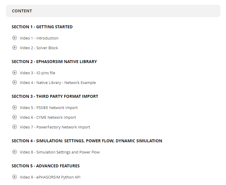
Real-time simulation techniques also confirm that new systems meet rigorous aviation standards. Hardware-in-the-Loop (HIL) testing reveals how well controllers and physical elements interact under near-instant feedback. Software-in-the-Loop checks algorithmic performance, providing critical data on responsiveness and fault tolerance. By evaluating multiple scenarios in a controlled virtual setup, teams maintain predictable costs and compress validation schedules. This level of readiness can smooth the final certification process and sharpen competitive positioning for new aircraft offerings.

Trends Driving More Electric Aircraft Advances


Many engineers are looking toward higher voltage frameworks and improved battery chemistries to handle longer ranges or heavier payloads. Distributed propulsion concepts are also maturing, in which multiple electric thrusters function as integrated systems to optimize flight control and reduce structural weight. Some programs lean on hybrid-electric architectures that combine conventional powerplants with partial electrification for extended missions. This selective approach keeps fuel use in check while adopting electric-based technologies where they deliver the strongest value.

Refinement of thermal management remains a priority, particularly as power electronics grow more complex and battery densities increase. Validation campaigns often involve specialized testing labs where components are pushed to their operational limits. These tests measure factors such as reliability, performance under various loads, and overall material resilience. Research groups and private organizations alike see the appeal in designs that balance cost, sustainability, and ease of certification. Achieving that balance requires a well-structured plan for testing, supply chain management, and continued optimization.

Accelerating MEA Projects with Real-Time Approaches


Organizations exploring More Electric Aircraft seek reduced emissions, flexible upgrade paths, and tangible returns on investment. High-voltage architectures, electric actuation, and integrated avionics can significantly lower fuel consumption and routine service burdens. Real-time simulation drives faster learning cycles, catching problems early and guiding better decisions on hardware layouts or control logic. These methods also help address the complexities of regulatory compliance and market expectations.

Engineers and R&D leads across aerospace sectors now view MEA as a practical path for smaller carbon footprints, stronger flight performance, and cost-conscious production. Many turn to specialized simulation platforms to validate subsystem designs under rigorous conditions, refine prototypes, and shorten time to deployment. The shift toward electrified operations calls for specialized expertise, thorough testing, and tools that confirm each stage of development meets aviation standards.

OPAL-RT brings deep experience in this domain, offering flexible solutions for Hardware-in-the-Loop testing and high-performance real-time simulation. Our platforms integrate seamlessly with power electronics, control algorithms, and advanced modeling workflows. As you plan or expand your MEA projects, OPAL-RT solutions can support your most complex validation goals, providing precise, scalable, and modular capabilities to confirm the performance of next-generation aircraft. Work with OPAL-RT to test, refine, and deliver your electrified aviation concepts with confidence.

Frequently Asked Questions

MEA approaches lower weight by replacing heavy mechanical elements with electrical systems. This shift supports more aerodynamic designs and helps engines run more efficiently, resulting in noticeable fuel savings over an aircraft’s operational life.


Real-time simulation creates a virtual model of power flows, actuator responses, and aircraft behavior. Engineers test new concepts before physical prototypes, finding and fixing design issues early while lowering overall project costs.


Yes. Many hybrid designs use electric subsystems for partial propulsion, auxiliary drives, or actuation. Applying MEA components can reduce fuel burn, cut noise, and make it easier to scale designs for longer missions.


Electric actuation supports any segment aiming for simpler maintenance, lighter structures, or modular upgrades. This can include commercial carriers, defense platforms, urban air mobility vehicles, and UAVs.


Projects can move faster when real-time simulation and well-integrated designs are involved. Thorough testing and clear documentation streamline the approval process, making it simpler to demonstrate compliance. 


Analog vs Digital Simulation: Advanced Real-Time Guide

Organizations in automotive, aerospace, and power systems often face high-stakes decisions when replicating complex signals. The right simulation strategy can reduce design risk, protect budgets, and unify technical teams across the organization. Senior engineers, R&D managers, and technical leads who need reliable, real-time data on circuit performance or embedded software behavior can gain an advantage by selecting the most effective simulation approach for their goals. This overview compares analog and digital simulation methods, offers concrete examples of how each is used, and clarifies the value of integrating both in a unified hardware-in-the-loop (HIL) platform.

Why Simulation Strategies Matter for Advanced Engineering


High-fidelity simulation is critical for professionals who build advanced power systems, automotive electronics, aerospace controls, and beyond. A robust simulation platform can validate hardware and software under realistic boundary conditions, reveal hidden design flaws, and support rapid iteration without risking physical equipment. By focusing on real-time performance and open integration with standard modeling tools, engineers and technical leaders can streamline testing, meet stringent safety requirements, and stay ahead of unexpected changes.

Real-time simulation aligns with product deadlines and mitigates the need for expensive prototypes. It also clarifies system behavior for cross-functional teams—from software developers verifying code to hardware specialists optimizing circuit topologies. Thorough exploration of analog and digital simulation ensures projects leverage the right mix of continuous signal analysis and discrete logic checks.

The Fundamentals of Analog Simulation


Analog simulation uses continuous signal models to represent varying voltages and currents in real time. Rather than looking at on/off or binary states, analog methods treat signals as uninterrupted waveforms, providing a direct view of physical phenomena.

Senior engineers working on power conversion, sensor feedback loops, or control circuitry often prefer analog methods because these techniques capture small voltage shifts, noise, and temperature effects that can alter performance. Accurate waveforms matter when verifying stability in operational amplifiers, analyzing electromagnetic interference, or confirming that filtering components function properly under load.

Development cycles benefit when teams can exercise an analog simulation model with different operating conditions and boundary parameters. This deeper visibility fosters confidence that a design will respond properly to variations in load, temperature, or supply voltage. Engineers can then reduce guesswork during prototyping and deliver more reliable hardware for subsequent testing phases.

“Some combine both methods through hybrid simulation to capture continuous elements alongside discrete ones.”

Key Applications of Analog Simulation


Analog methods suit scenarios where continuous signals play a major role. Examples include:

  • Power generation & transmission: Utilities often replicate grid fluctuations in high-voltage networks to confirm that converters and other equipment can withstand fault conditions. Analog simulation supports investigations of harmonic distortion and grid stability when integrating renewable sources.
  • Aerospace controls: Flight control engineers test inertial guidance boards or sensor feedback loops to confirm that outputs remain stable across a range of stress factors. Analog waveforms show real voltage responses, allowing precise design improvements.
  • Industrial automation: Production lines and robotic arms rely on constant signaling for actuators, drives, and sensors. Analog simulation helps validate motor drivers, reduce power consumption, and maintain consistent performance.
  • Automotive electronics: Hybrid and electric vehicles often incorporate complex powertrains. Analog simulation assists with evaluating converter topologies, sensor interfaces, and battery management circuits under varying loads.
  • Research & academia: Labs focused on electromagnetic interactions, high-frequency applications, or advanced control algorithms often require analog simulations to verify ideas before building physical prototypes.
  • Consumer electronics: Engineers designing wearables, smartphones, or gaming devices use analog techniques to check amplifier performance, battery management, and thermal behavior.

These activities target real signal integrity at every stage. Precisely modeling operational amplifiers, feedback circuits, and filters removes guesswork. Engineers can anticipate design challenges ahead of production, cutting down on multiple prototyping rounds.

The Fundamentals of Digital Simulation


Digital simulation deals with discrete states—often represented as binary logic or multi-level signals. Instead of examining continuous voltage waveforms, this method tracks changes at defined time steps, which suits software-driven operations, microcontrollers, or digital signal processing tasks.

R&D and test engineers favor digital simulation to verify firmware logic, communication protocols, and timing across large systems. Code-level issues can be identified before final hardware arrives, sparing teams from rework. By replicating on/off states, engineers can confirm that software triggers happen at precise intervals, data formatting is correct, and clock signals align with design requirements.

Digital simulations tend to run faster because they skip the detailed math of continuous waveforms, making it easier to apply automation in regression testing. This reduces the chance of missing corner cases in logic flows. Many industries rely on digital simulation to confirm reliability in devices that handle data transmission, user interfaces, or sensor sampling.

“At OPAL-RT, decades of expertise and a commitment to excellence guide our delivery of open, scalable, and high-performance solutions for hardware-in-the-loop, software-in-the-loop, and beyond.”

Key Applications of Digital Simulation


Projects involving digital logic or large codebases often benefit from digital methods:

  • Microprocessor design: Semiconductor firms run register-transfer-level checks to confirm timing for signals that move between functional blocks. Early detection of errors avoids costly chip re-spins.
  • Networking & communications: Engineers validate protocols to confirm proper handshakes, error checking, and packet transfers. This approach detects cryptic bugs in advanced data routing and industrial IoT systems.
  • Automotive control units: Complex firmware in battery management, ADAS (Advanced Driver Assistance Systems), and body electronics requires thorough verification. Digital simulation flags concurrency issues or missed interrupts that jeopardize safety.
  • Industrial robotics: Controller software drives motion planning, sensor fusion, and operational checks. Digital simulations of these logic flows foster consistent performance in manufacturing environments.
  • Medical devices: Regulatory standards demand that implantable devices and patient monitors go through rigorous testing. Digital simulation confirms code reliability under boundary conditions before clinical trials.
  • Consumer device firmware: Features like touchscreen response, battery optimization, and data encryption can be modeled with discrete logic to reduce firmware rollbacks and ensure a stable user experience.

A careful digital testing approach saves time and budget by avoiding multiple hardware prototype runs. It also encourages collaboration between embedded software teams and hardware designers.

Core Differences Between Analog and Digital Simulation


The main distinction lies in signal representation. Analog models continuous waveforms, capturing every fractional change in current or voltage. Digital methods rely on discrete states or steps. The choice depends on the system’s primary nature:

Aspect

Analog Simulation

Digital Simulation

Signal Representation

Continuous waveforms, varying over time

Discrete states (often binary or multi-level)

Typical Use Cases

Circuit stability, noise, sensors

Firmware logic, communication protocols

Accuracy vs. Speed

High precision, potentially slower execution

Faster execution, less granularity in analog detail

Tools/Methodologies

SPICE-like solvers, real-time analog platforms

HDL-based verification, logic analyzers

Industry Examples

Power grids, sensor feedback loops

Microprocessor design, ADAS firmware


Some organizations combine both. A hybrid approach allows analog waveforms to coexist with discrete logic states. This can be essential for large systems—consider an automotive powertrain with both analog sensor signals and digital microcontrollers. Engineers benefit from the ability to evaluate everything in one place, especially when real-time hardware-in-the-loop test setups bring these processes closer to actual operating conditions.

Selecting the Right Method


Senior engineers and technical leads often weigh the following factors when deciding on analog or digital simulation:

  • Nature of the signals: Systems based on continuous voltages or currents often favor analog methods. Digital logic or state-based design calls for binary-style modeling.
  • Scope and complexity: Large systems with multiple microcontrollers could benefit from digital simulation, while subsystems that include intricate circuits need analog detail.
    Time and cost constraints: Digital simulations usually run faster and may allow more tests per hour. Analog simulations can be more computationally intense, yet reveal subtle phenomena missed by discrete modeling.
  • Stage of development: Early conceptual work might focus on high-level digital checks. Later refinement might need analog detail for final fine-tuning of power electronics or sensor loops.
  • Integration with Hardware-in-the-Loop: Real-time HIL often combines analog I/O channels with digital interfaces to represent every aspect of the design. One consolidated platform saves time and fosters more meaningful collaboration among mechanical, electrical, and software teams.

In many cases, an organization will pair both methods to cover all design layers. Digital checks can validate logic flow and firmware timing, while analog checks confirm that real signals stay within safe margins.

Emerging Methods and Tools in Simulation


Technical leaders see new avenues in simulation through cloud-based resources, machine learning-assisted modeling, and unified real-time platforms that handle both analog and digital signals. Parallel processing on FPGAs (Field-Programmable Gate Arrays) expands the potential to run high-fidelity simulations at a rate that keeps up with real hardware. This is particularly valuable for testing power electronics, advanced battery systems, and complex microgrids.
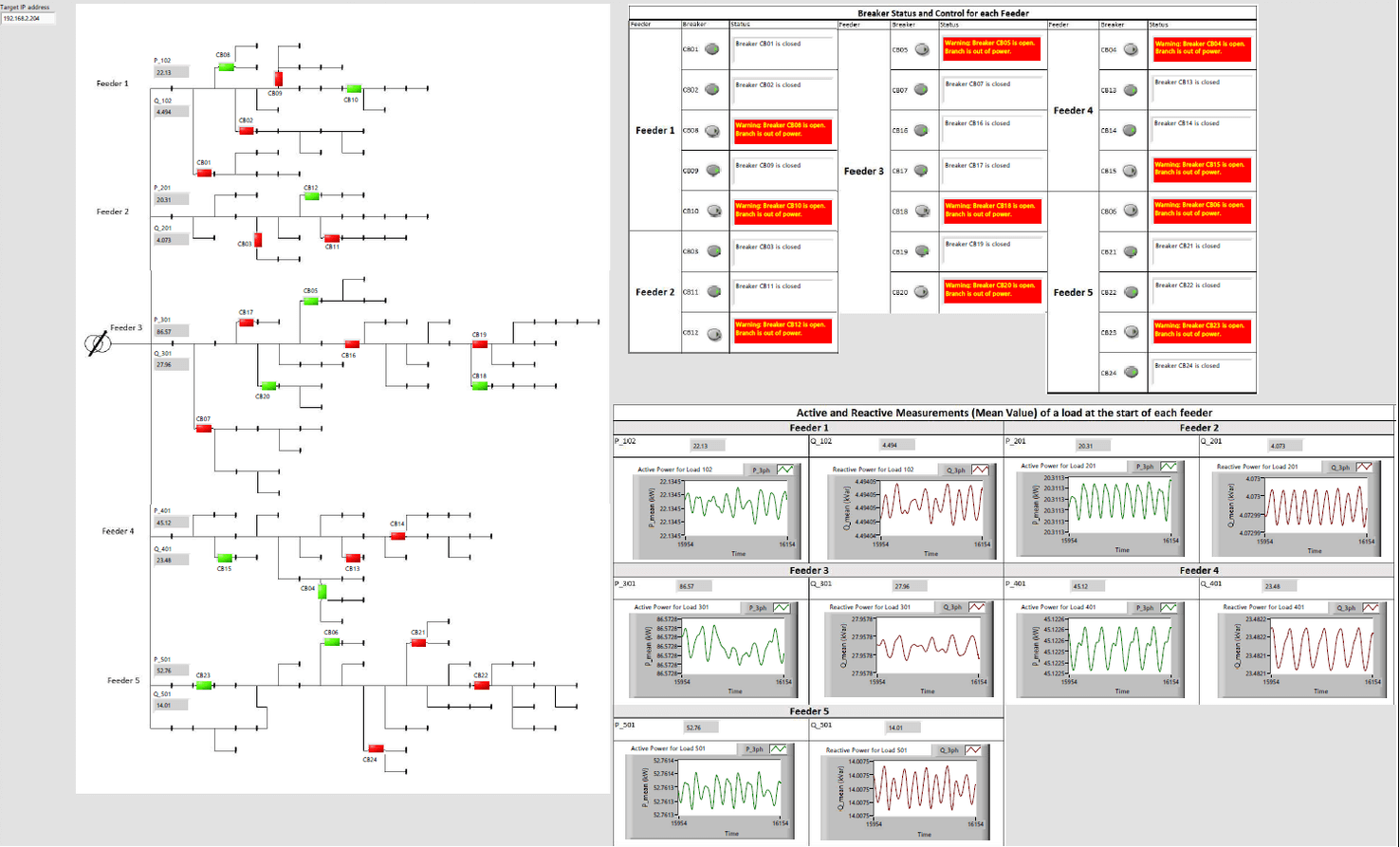
Multi-domain models bring mechanical, electrical, and software elements together so engineers don’t have to bounce between separate tools. This creates a single source of truth, reducing manual alignment across teams. Open software architectures also let smaller teams adopt real-time simulation without major up-front investment in proprietary solutions.

By selecting modern real-time simulation platforms, engineers gain:

  • Scalable performance: Configure processing capability based on project scope.
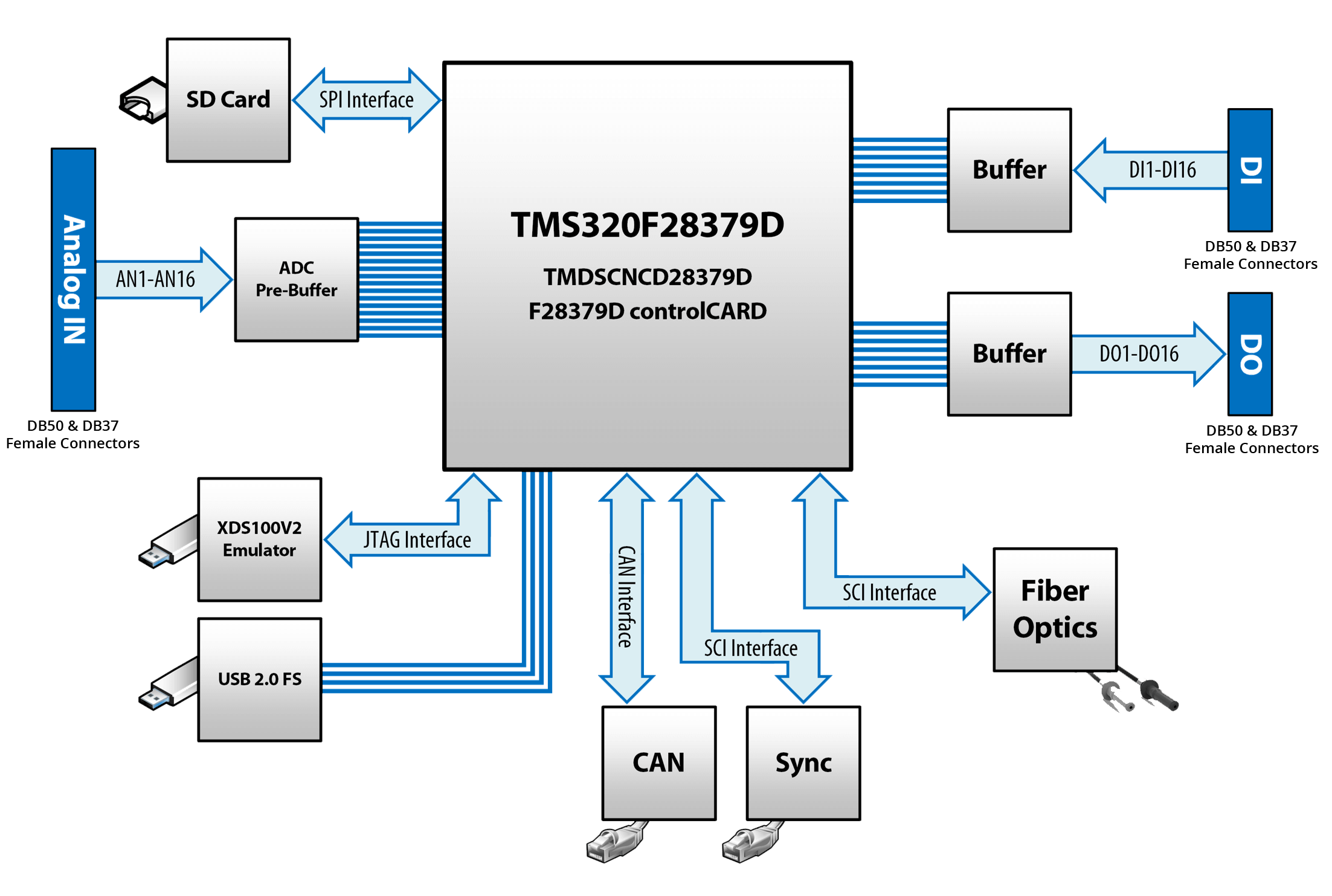
  • Open toolchains: Use industry-standard modeling environments (MATLAB/Simulink, FMI/FMU, Python) without vendor lock-in.
  • High-fidelity results: Benefit from specialized modules for power electronics, automotive control, or aerospace.
  • Collaboration across locations: Work with colleagues in remote labs or different departments by sharing the same validated models.

Organizations that integrate these solutions often discover quicker time-to-market cycles and a sharper ability to handle late-stage changes or new requirements.

Real-Time Simulation 


OPAL-RT provides real-time solutions that match the needs of senior simulation engineers, R&D managers, and system architects looking to validate complex designs. Our platforms combine analog precision and digital scalability, making them ideal for automotive powertrains, grid emulation, flight controls, and other demanding applications.

  • Hardware-in-the-Loop (HIL) test: Verify hardware interactions early by connecting physical components or control units to real-time simulators. This reveals system-level behavior, bridging analog signals and digital logic in a single setup.
  • Open architecture: Seamlessly integrate with MATLAB/Simulink, Python, and established toolchains. Our solutions address specific industry standards, including communication protocols for automotive, utilities, and aerospace.
  • Scalable performance: Start with a smaller configuration for initial testing and ramp up as projects grow more complex. This accommodates emerging technologies like autonomy or wide-bandgap semiconductors.
  • High-fidelity FPGA capabilities: Capture fast transients and microsecond-scale events with FPGA-based simulators. This approach is essential for power electronics, propulsion systems, and advanced sensor modeling.
  • Ease of collaboration: Let cross-functional teams validate designs from a common interface, share data, and align on real test outcomes. This cuts iteration time and clarifies technical debates.

Many companies turn to OPAL-RT to accelerate their development roadmaps without sacrificing depth in their testing programs. By bridging analog and digital simulation, our solutions help organizations confirm design integrity, meet regulatory milestones, and free up engineering resources for the next generation of prototypes.

Bringing Analog and Digital Together for Greater Impact


Analog simulation captures the continuous signals found in power circuits, filters, and feedback loops. Digital simulation replicates the discrete logic of microcontrollers, firmware, and communication networks. Each approach has unique strengths, and many projects require both. Engineers focused on real-time, high-fidelity tests can integrate these methods in a unified platform that offers:

  • Continuous and discrete components: Merge analog waveforms and digital logic in the same simulation to reflect how physical systems truly operate.
  • Scalable test coverage: Run thousands of digital checks alongside high-precision analog models without losing synchronization or clarity.
  • Rapid iteration: Catch errors in code or circuit design before building multiple hardware prototypes.
  • Consistent development flow: Maintain a single model across R&D, QA, and manufacturing.
  • Improved cross-disciplinary collaboration: Connect mechanical, electrical, and software engineers in one environment for faster decision cycles.

Real-time simulation tools ensure that neither analog nor digital aspects are overlooked. This is essential for aerospace flight control boards with sensor signals feeding complex control algorithms, or for large power grids where digital relays must coordinate with analog current inputs.

Move Forward with Real-Time Confidence


Senior engineers, researchers, and technical leaders who master both analog and digital simulation gain an upper hand in meeting deadlines and fulfilling strict reliability targets. These methods shine brightest when combined within a hardware-in-the-loop environment that mirrors the final application.

At OPAL-RT, decades of real-time simulation expertise support engineers in pressing industries: automotive electrification, aerospace guidance, academic research, and more. Our open and scalable solutions bring high-fidelity results to each stage of development. Seamless integration with standard modeling tools empowers engineers to validate complex systems—analog or digital, without reinventing their workflows.

Teams can adopt our flexible platforms to explore power electronics, advanced driver assistance, flight control, or microgrid emulation in a single, proven solution. The outcome is confidence in test results, accelerated product launches, and efficient use of engineering budgets.

Experience real-time precision that spans analog waveforms and digital logic. Face your next project with a comprehensive approach that supports robust designs and meaningful outcomes. Contact OPAL-RT to see how we can help you refine simulation workflows, reduce hardware prototypes, and deliver advanced systems ready for the demands of modern engineering.

Frequently Asked Questions

Real-time simulation accommodates continuous waveforms and discrete states in a single setup. Engineers can confirm performance for analog circuits and digital logic together, cutting development cycles and reducing hardware rework.


Some designs feature sensor feedback loops while relying on microcontrollers or digital signal processing. Merging both simulation types ensures every signal—continuous or discrete—is validated accurately for smoother integration.


Sectors like automotive, power generation, aerospace, and industrial controls rely on these methods to validate complex systems under realistic conditions. Real-time testing is especially vital where safety, reliability, or compliance is paramount.


Hardware-in-the-loop connects physical components to simulated signals, replicating operational scenarios without relying on full prototypes. This approach highlights design flaws early and supports iterative refinements at lower cost.


Software packages such as SPICE-like solvers address analog waveforms, while HDL-based solutions analyze digital states. Modern real-time platforms combine both capabilities for a unified, high-fidelity environment.