RMS vs EMT Simulation for IBRs Explained for Power System Engineers

A split‑second voltage dip can cost a solar plant its revenue target for the month, yet predicting that dip starts with choosing the right simulation approach.


Real‑time validation of inverter‑based resources (IBRs) hinges on accurately representing both electrical dynamics and embedded control logic. Two techniques dominate the conversation: root‑mean‑square (RMS) phasor simulation and electromagnetic‑transient (EMT) simulation. Each method excels at specific time scales, study types, and hardware‑in‑the‑loop (HIL) workflows. Matching the method to the challenge speeds studies, keeps capital budgets under control, and unlocks crucial operational insights for grid operators and OEMs alike.

“The main difference between RMS and EMT simulation is the time resolution each uses, which dictates the physical detail each can represent.”


Understanding the Core Differences Between RMS and EMT Simulation


The main difference between RMS and EMT simulation is the time resolution each uses, which dictates the physical detail each can represent. RMS simulation averages electrical waveforms over an entire cycle, giving you fast, system‑wide insight into steady‑state voltage, current, and power flows. EMT simulation resolves the actual waveform at micro‑ to millisecond intervals, revealing sub‑cycle harmonics, converter switching events, and detailed protection interactions. Because EMT does not assume sinusoidal balance, it captures asymmetrical faults, converter phase‑locked‑loop behavior, and high‑frequency resonance that RMS phasors inherently smooth out. When deciding on RMs vs EMT simulation, consider not only the study objective but also the fidelity demanded by regulatory guidelines, cybersecurity constraints on control code, and the hardware available in your test lab.


How EMT Simulation Helps Solve Transient Stability in IBR Testing


EMT (Electromagnetic Transients) simulation operates at the timescale required to capture converter behavior, high-frequency switching, and network dynamics that unfold in milliseconds or less. This resolution makes it essential for engineers tasked with validating grid-forming inverters, power-electronic controllers, and other converter-dominated systems.

Capturing Sub‑Cycle Harmonics


Inverter switching generates high-order, non-integer harmonics that can stress filters, inject distortion into transformers, or trip protection devices. These effects typically occur within a single electrical cycle and often bypass detection in RMS-based tools. EMT simulation tracks the propagation of these harmonics from the converter through transformers, cables, and relays, allowing teams to test filter tuning and fault detection logic before equipment is energized.

Protecting Converters During Faults


Converter protection firmware often responds to single-line-to-ground faults within two milliseconds or less. EMT simulation replicates the exact sequence of control-layer behavior—current limiting, gate blocking, and protective shutdowns—under precise voltage and current conditions. Engineers verify that IGBT and SiC modules stay within thermal and current boundaries while maintaining grid-code compliance under fault stress.

Validating Complex Control Logic


OEMs often supply control code in proprietary formats, including compiled C, FPGA bitstreams, or encrypted libraries. EMT real-time simulation platforms allow these blocks to be tested without source-code exposure. Engineers observe how firmware reacts to varying point-on-wave conditions, anti-islanding triggers, and impedance shifts, ensuring that algorithms coordinate properly with system-level protection and synchronization logic.


When RMS Simulation Is Suitable for Steady‑State IBR Scenarios


RMS-based phasor tools still hold strategic value. Their coarse resolution enables quick, high-volume scenario sweeps where transient detail is not required. For long-term planning and broad interconnection screening, RMS remains the most efficient approach.

Long‑Term Voltage Profiles


Simulating seasonal or hourly variations in feeder voltage requires volume, not precision. RMS tools can evaluate thousands of operating points in minutes. Engineers determine optimal capacitor placements, study load shifting strategies, and check the impact of solar intermittency without tracking sub-cycle noise.

Utility‑Scale Planning Studies


Transmission planners use RMS simulation for grid interconnection analysis because it integrates directly with existing databases and regulatory toolchains. The format simplifies study setup and quickly identifies thermal overloads, voltage drops, and transformer tap conflicts under contingency scenarios.

Cost‑Sensitive Iterative Studies


When engineers must test multiple design options within short regulatory timeframes, RMS tools reduce resource strain. Tap settings, grounding topology, and capacitor locations can be adjusted and retested quickly without tying up real-time hardware or simulation engineers.

EMT vs. RMS Applicability

Scenario

EMT Simulation

RMS Simulation

Transient stability

Essential (μs resolution)

Inadequate

Harmonics analysis

Required (waveform capture)

Limited accuracy

Steady-state planning

Overkill

Optimal (fast computation)


Practical Use Cases for EMT Simulators in Modern Grid Design


As IBR integration scales and grid dynamics become more sensitive, traditional RMS models can miss critical behaviors that jeopardize system stability. EMT simulators are now essential tools for replicating the speed, complexity, and non-linearities of modern power electronics. Engineers use these simulators not only to validate converter designs but also to investigate specific operating scenarios where control decisions are made in microseconds.

  • Fault‑Induced Delayed Voltage Recovery (FIDVR): Examine how air‑conditioner motor stalling interacts with large solar‑PV ramp‑downs during low‑voltage events.
  • Grid‑Forming Inverter Commissioning: Test synthetic inertia algorithms and droop settings under high renewable penetration.
  • Battery‑Energy‑Storage Black‑Start: Validate that a BESS can close onto a dead bus, build voltage, and accept synchronous machines without mis‑tripping.
  • Point‑on‑Wave Switching of STATCOMs: Assess inrush and DC offset by modeling breaker pre‑insertion resistors at a microsecond scale with an EMT simulator.
  • High‑Speed DC Fault Isolation in HVDC Links: Verify metal‑oxide varistor coordination and hybrid breaker timing during pole‑to‑ground faults on multi‑terminal DC grids.

Each of these use cases highlights where RMS phasor models fall short and EMT simulators become mission-critical. Whether you’re building black-start capability into a battery system or validating switching logic on a STATCOM, EMT simulation captures the speed and detail needed to avoid late-stage redesigns and costly field errors.


Key Performance Tradeoffs in RMS and EMT Simulation for IBRs


Choosing between RMS and EMT isn’t just a question of accuracy; it’s a question of scale, runtime, and engineering workflow. Understanding the tradeoffs involved helps simulation teams allocate their resources efficiently while meeting interconnection and compliance requirements. From solver precision to project turnaround time, each method brings strengths and limitations that matter in different stages of the validation cycle.

  • Time Step vs. Network Size: EMT steps in microseconds, yet shrinks allowable system scale; RMS steps in milliseconds and scales to thousands of buses.
  • Hardware Requirements: EMT often needs FPGA acceleration; RMS runs on conventional CPUs, trimming capital cost.
  • Data‑Set Granularity: EMT waveforms create terabytes of output needing careful archival; RMS yields concise datasets suited to long‑term trending.
  • Engineer Productivity: RMS supports automated contingency screening; EMT demands hands‑on tuning of damping, step size, and solver parameters.
  • Compliance Objectives: EMT is essential for grid‑code clauses on flicker, high‑frequency oscillations, and short‑circuit current; RMS satisfies capacity‑planning rules.

Balancing these tradeoffs ensures that simulation efforts remain aligned with budget constraints, project timelines, and technical specifications. When RMS and EMT simulations are strategically applied, engineers gain the flexibility to validate what matters most, without overextending team capacity or hardware budgets.

Choosing the Right EMT Simulation Software for System‑Level Projects


Selecting EMT simulation software begins with defining the smallest time constants that matter to your study. If converter protection acts within 50 µs, ensure the solver supports sub‑10 µs steps on hardware you already use. Look for software that exchanges FMI/FMU objects, so plant‑level controllers written in Modelica or Simulink can co‑execute with C‑based device firmware. Library breadth should span overhead lines, cable frequency‑dependent parameters, and built‑in phasor domain solvers for co‑simulation. Finally, confirm cybersecurity features such as hashed model distribution and encrypted code‑injection paths to keep OEM intellectual property private.

“With OPAL‑RT, you study converter behavior at microsecond resolution on the same open platform you already trust for steady‑state analysis, without adding extra hardware.”


How OPAL‑RT Supports RMS and EMT Simulation for IBR Validation


OPAL‑RT’s open‑architecture platforms allow you to load RMS phasor models and microsecond‑level EMT models on the same hardware, switching between them without rewiring a single connector. The Blackbox Interface injects encrypted OEM control code directly into the simulator, so converters behave exactly as they will in the field while the intellectual property remains protected. Integrated FPGA acceleration achieves sub‑10 µs steps for high‑frequency switching studies, while multicore CPUs carry out large‑scale RMS load‑flow sweeps during overnight batch runs. With OPAL‑RT, you study converter behavior at microsecond resolution on the same open platform you already trust for steady‑state analysis, without adding extra hardware. That consistency shortens project timelines, trims validation costs, and gives engineers confidence that grid‑connection requirements will be met on the first submission.

Engineers and innovators rely on real‑time simulation to accelerate development, reduce risk, and push the limits of what is possible. At OPAL‑RT, we bring decades of expertise and a passion for innovation to deliver the most open, scalable, and high‑performance simulation solutions in the industry. From Hardware‑in‑the‑Loop testing to AI‑ready cloud simulation, our platforms help you design, test, and validate with confidence.

Common Questions About RMS vs EMT Simulation for IBRs

RMS phasor tools screen thousands of contingencies quickly, so planners catch thermal or voltage violations early, while EMT is reserved for detailed converter or protection studies requiring microsecond fidelity.


Modern simulators use encrypted blobs and secure memory spaces, allowing original firmware to run in real time without exposing proprietary algorithms to third parties.


RMS models average waveforms over whole cycles, so they miss sub‑cycle harmonics; engineers typically shift to EMT once resonance risks surface.


Hardware acceleration sustains sub‑10 µs solver steps, which are essential for capturing high‑frequency switching and protection logic in converters.


RMS studies clear steady‑state interconnection milestones quickly, while EMT proofs satisfy fast‑transient clauses in newer grid codes, letting projects proceed through regulatory gates without rework


Mastering Grid Forming vs Grid Following in Real-Time Testing

A power system only stays healthy if every inverter agrees on who leads and who follows, and that simple truth decides everything from voltage quality to blackout risk.


Why Grid Forming Inverter vs Grid Following Matters for System Stability


The main difference between grid-forming inverters and grid-following inverters is the source of their voltage reference; grid-forming devices create it, while grid-following devices wait for it. This single distinction drives stability. When an inverter establishes its own frequency and voltage, it can anchor weak grids, ride through faults, and share power with other sources even if the utility connection disappears. Grid following units, by contrast, synchronize to an existing waveform. They behave like precision current sources and withdraw as soon as that reference falters, so they cannot keep an islanded microgrid alive on their own.

Sudden disconnection events illustrate the stakes. If a wildfire isolates a feeder, grid-forming inverters hold frequency until crews close the breaker. If the same feeder relied only on grid-following units, all generation could trip, starving customers of power. At utility scale, a shrinking share of synchronous machines means fewer spinning masses to absorb shocks; grid forming control restores fast inertia electronically, smoothing frequency ramps and preventing protective trips. For engineers tasked with compliance under IEEE 2800 or meeting North American Electric Reliability Corporation (NERC) ride‑through profiles, choosing the right control mode is now a frontline design decision.


Key Differences Between Grid Forming and Grid Following Inverters


The main difference between grid-forming and grid-following topologies lies in the control strategy, but this choice cascades into hardware sizing, protection settings, and certification workflows. The comparison below highlights four areas engineers weigh during project planning.

Control Reference and Synchronization


Grid-forming inverters synthesize a voltage waveform internally, often with a virtual oscillator, and then push that reference onto the bus. Grid-following devices first measure the grid voltage via a phase‑locked loop, then inject current shaped to that reference. Because grid-forming units do not hunt for an external phase signal, they react in milliseconds when line conditions change, holding service in microgrids or on weak feeders. Grid following needs a stable grid to function, so it excels in strong transmission zones but yields authority when faults break that link.

Frequency and Voltage Support


A grid-forming inverter adjusts its frequency based on momentary power imbalance—mimicking the inertial response of a synchronous generator—while also drooping voltage with reactive power to share VAR duty across peers. This dual role supplies primary frequency regulation and voltage-var control without extra governors. Grid following units offer dynamic reactive support through adjustable power‑factor targets, but cannot police system frequency; their PLL will ride the drift instead of arresting it. That limitation pushes planners to add battery‑based flywheels or synchronous condensers if grid following dominates.

Fault Ride‑Through Behavior


Because grid-forming control loops track their own reference, they continue producing voltage during voltage sags, injecting the current needed by protection studies. The current magnitude is still limited by semiconductor ratings, yet the phase remains well‑behaved, reducing negative‑sequence stress on machines. Grid-following inverters experience PLL loss of lock during deep sags, so they may cease output precisely when the network requires support, triggering cascading trips. Advanced PLLs help, but they still trail grid-forming resilience.

Impact on Weak Grids


In feeders with high X/R ratios that shift resonances into critical frequency bands, grid-forming inverters suppress oscillations by establishing the dominant voltage source impedance. Conversely, grid-following inverters interact with this impedance and amplify voltage flicker, particularly when multiple units operate in parallel at a common coupling point.

“The main difference between grid-forming inverters and grid-following inverters is the source of their voltage reference; grid-forming devices create it, while grid following devices wait for it.” 

When to Use Grid-Forming Inverters in Power System Design


Grid-forming inverters shine in any project aiming for self‑sufficiency or resilience. Remote mines, islanded military bases, and high‑renewable microgrids keep lights on during outages by assigning at least one inverter to form the grid. Hybrid plants that couple photovoltaic arrays with battery energy storage also lean on grid-forming control to deliver synthetic inertia and reserve headroom for frequency containment. Onshore wind farms connected through weak AC lines gain export headroom when the first turbines upgraded to grid-forming firmware stabilize voltage at the point of interconnection. Utilities commissioning HVDC links cite the same benefit: voltage‑sourced converters operating in grid-forming mode smooth power swings when DC faults clear.


How Grid Forming Supports Renewable Integration and Islanded Grids


Variable renewables introduce fast power ramps and low short-circuit currents, challenging legacy protection schemes. Grid-forming inverters address this through virtual synchronous machine (VSM) control, delivering fault currents compliant with grid-code templates (e.g., LVRT requirements) and stabilizing frequency during generation surges. In islanded grids, sudden load shifts (e.g., sawmill startups) cause frequency deviations, but grid-forming droop control corrects these within 200–500 ms—well below equipment tolerance thresholds (±0.5 Hz). Unlike synchronous machines, these sources activate in <2 seconds, enabling fuel-free cycling for load-following. Studies, including ERCOT simulations and Hydro Tasmania deployments, demonstrate 10–15% reserve margin reductions when grid-forming fleets replace synchronous condensers, lowering capex while reallocating spinning reserves to revenue service.

Common Challenges in Grid Forming Inverter Testing and Validation


  • Model availability: Manufacturers guard proprietary firmware, so engineers lack detailed transfer‑function data.
  • Controller‑hardware mismatch: Lab prototypes may run on digital signal processors, unlike the final field units, skewing timing.
  • Network strength emulation: Replicating weak‑grid impedances at scale requires high‑bandwidth amplifiers or electromagnetic transient (EMT) solvers.
  • Multi‑vendor coordination: Mixing grid forming and grid following suppliers complicates closed‑loop stability assessments.
  • Compliance traceability: Demonstrating that real‑time testing matches IEEE 2800 waveforms demands synchronized measurement across controllers.
  • Resource footprint: Full EMT simulation of a 300‑MW plant taxes CPU resources unless the platform splits tasks across FPGA and processor cores.
  • Iterative firmware updates: Each patch alters control coefficients, requiring regression tests to lock trip settings before site roll‑out.


How OPAL‑RT Supports Grid Forming and Grid-Following Simulation


OPAL‑RT solves these testing pain points by letting you load the original equipment manufacturer’s control code into a protected Blackbox Interface that runs on FPGA‑CPU co‑simulation hardware. Intellectual property stays encrypted, yet you still probe inputs and observe outputs in real time, so grid-forming inverter vs grid following scenarios reach full EMT fidelity without extra cabinets. Multi‑rate solvers handle microsecond‑level switching alongside millisecond network transients, giving you sub‑100‑µs latency for hardware‑in‑the‑loop studies. Because the platform connects through standard protocols, you integrate SCADA, phasor measurement units, and protection relays on the same bench, trimming weeks from model‑validation cycles and cutting test‑lab overhead. Utilities, independent power producers, and OEMs rely on this open approach to vet grid forming compliance, shorten interconnection studies, and roll out firmware confident that field performance will match the bench.

Engineers and innovators around the globe are turning to real‑time simulation to accelerate development, reduce risk, and push the boundaries of what is possible. At OPAL‑RT, we bring decades of expertise and a passion for innovation to deliver the most open, scalable, and high‑performance simulation solutions in the industry. From hardware‑in‑the‑loop testing to AI‑ready cloud simulation, our platforms empower you to design, test, and validate with confidence.


“OPAL‑RT solves these testing pain points by letting you load the original equipment manufacturer’s control code—line for line—into a protected Blackbox Interface that runs on FPGA‑CPU co‑simulation hardware.”


Common Questions About Grid Forming vs Grid Following in Real-Time Testing

Grid forming units create their own voltage reference, acting as voltage sources, while grid following units synchronize to an existing reference and inject current accordingly. This control choice determines stability roles and protection settings.


Hardware prices are converging; the premium now lies mostly in firmware development and certification. As volumes rise, cost differences narrow, especially when avoided spinning‑reserve credits offset capital outlay.


Yes. Many hybrid projects assign a subset of inverters to grid-forming mode for stiffness while leaving the remainder in grid following mode for dispatch flexibility. Proper tuning and EMT testing prevent control interaction.


Grid forming tests require weak‑grid impedance models, virtual inertial events, and islanding scenarios, while grid following tests focus on phase‑locked loop robustness and var support. Both still need fault ride‑through checks.


IEEE 2800, IEC 60034‑32‑1, and emerging ENA guidelines address synthetic inertia, frequency‑watt response, and low‑inertia support. Many regional grid codes reference these documents for acceptance.


How BESS Enhances Grid Performance

A single millisecond can decide whether your grid remains lit or slips into costly downtime. You need energy reserves that respond as quickly as your protection relays, stay secure under probing regulation, and deliver measurable payback to investors. That urgency fuels interest in what is a battery energy storage system (BESS) and how it shifts grid operations from reactive correction to proactive stability. This piece speaks directly to engineers and business leaders seeking faster time-to-value, lower lifetime cost, and confidence that every line of code protects intellectual property while passing the harshest compliance checks.


Understanding the Basics of a Battery Energy Storage System


Every BESS combines electrochemical cells, power converters, and sophisticated control logic to capture excess generation and discharge it on command. You gain a modular asset capable of storing kilowatt-hours when solar ramps up and releasing them within cycles when load rises. Four core elements define what is BESS: the battery pack, a bidirectional inverter, thermal management, and a supervisory controller that sets charging limits and state-of-charge targets. Comparison studies show that lithium-ion chemistries currently balance energy density and cycle life most effectively, yet future deployments already test sodium-ion and solid-state designs for cost or safety advantages.

Behind the hardware, firmware orchestrates current flow, maintains cell balance, and publishes data tags for SCADA integration. A well-tuned control stack manages degradation by throttling charge rates during high temperatures and rest periods, raising asset revenue through extended lifetime. Digital twins refined through hardware-in-the-loop rigs shorten firmware validation cycles, slashing commissioning risk for OEMs and utilities alike. When design moves from whiteboard to live grid, a secure interface, such as OPAL-RT’s black-box model wrapper, keeps proprietary algorithms hidden while still reproducing exact behavior.

“A single millisecond can decide whether your grid remains lit or slips into costly downtime.” 


How BESS Systems Enhance Grid Stability and Performance


Modern grids contend with abrupt renewable output swings, sub-cycle fault currents, and inverse inertia from power electronics. A well-planned BESS system answers each challenge through immediate active-power injection that counters frequency dips before conventional generators ramp. Precise reactive-power control also supports voltage at weak nodes, minimizing flicker complaints and helping distributed energy projects pass interconnection studies. Localized fast-frequency response from one plant aggregates across substations, effectively rebuilding the kinetic buffer once supplied by synchronous machines. Utilities that run stacked services—frequency regulation, ramp-rate smoothing, and spinning-reserve replacement—report payback periods under five years due to avoided penalties and ancillary market revenues.


Key Components of BESS Energy Management Systems


State-of-Charge Estimator


Accurate state-of-charge (SoC) tracking guides dispatch decisions and safeguards warranty commitments. Advanced Coulomb counting fused with Kalman filtering corrects sensor drift while accounting for temperature-dependent capacity losses. Adaptive models update in real time using impedance spectroscopy data, supplying operators with confidence that reserve margins are genuine megawatt-hours, not theoretical figures. A mismatched estimator risks premature shut-downs or deep discharges that erode cell life and investor returns.

Power Conversion System (PCS) Controller


The PCS bridges DC batteries and the AC grid through pulse-width-modulated IGBTs or SiC MOSFETs. Vector-current control maintains unity power factor or purposeful VAR support, switching within microseconds. Grid-forming firmware even establishes voltage when transmission outages isolate feeders, providing a stable point for solar inverters to follow. Secure real-time simulation lets engineers validate anti-islanding responses without exposing the proprietary modulation code shipped to customers.

Thermal Management Logic


Thermal runaway starts with a local hotspot, so every BESS includes closed-loop cooling and heating routines. Liquid or forced-air circuits react to cell temperature sensors, while predictive algorithms schedule conditioning based on forecast duty cycles. Maintaining a narrow thermal band extends cycle life and improves round-trip efficiency. Granular control also reduces parasitic loads, trimming operating costs over multi-year service agreements.

Cybersecurity Module


Grid codes now mandate layered defense across device, network, and cloud interfaces. Role-based authentication, encrypted firmware updates, and watchdog timers form the backbone of embedded security. A digital twin running on OPAL-RT allows penetration testers to probe the control surface safely, watching how intrusion detection flags abnormal command sequences. Findings feed directly into patched firmware before plant deployment, avoiding costly field retrofits.

Revenue Optimization Engine


An optional, yet increasingly popular, software layer forecasts price signals, computes degradation cost, and dispatches the battery to maximize net value. Machine-learning predictors sift wholesale price patterns and local demand charges to schedule charging windows. The engine then passes set-points to the PCS, continuously updating margins to respect warranty limits. When plugged into enterprise ERP systems, executives see transparent cash flows that justify further rollout across their fleets.

Critical Testing Procedures for Reliable BESS System Performance


Successful field performance begins in the lab, where rigorous validation spots latent faults long before energization. Test engineers face mounting pressure to complete thorough verification without extending project timelines or revealing confidential algorithms. The procedures below outline the most reliable path to confidence, each aligning with IEEE 2030.2 and IEC 62933 guidance. Following them helps manufacturers provide bullet-proof evidence to utilities and regulators.

  • Hardware-in-the-Loop Fault Ride-Through: Confirms inverter current injection under simulated voltage dips, ensuring grid-code pass status.
  • Communication Latency Measurement: Validates delay budgets for SCADA commands across Ethernet, serial, and IEC 61850 links.
  • Electromagnetic Immunity Sweep: Subjects control electronics to fast transients and radio-frequency interference, verifying proper shielding.
  • Accelerated Thermal Cycling: Cycles ambient temperature to expose solder fatigue and connector loosening that trigger field failures.
  • Aging Algorithm Verification: Runs extended SoC oscillations to check capacity fade prediction accuracy against real degradation.
  • Black Start Capability Test: Demonstrates PCS voltage-source mode and controlled island growth without synchronous machines.
  • Over-Current Protection Coordination: Evaluates relay settings using staged faults to confirm selective isolation and asset safety.

Completing each campaign inside a real-time simulator decouples controller stress from costly high-power stacks. Engineers replicate grid events at full resolution, pause execution to inspect variables, then resume without hardware resets. Investors receive data-rich reports that replace guesswork with quantified margins. Project schedules hold firm because iterative fixes occur in software, not on construction sites.


Protecting Manufacturer IP in BESS Systems Simulation


Original control code distinguishes one OEM from another, so exposure risk remains a constant concern. OPAL-RT addresses this worry through a black-box interface that accepts DLL, FMU, or compiled C while hiding the source. Time-deterministic wrappers call functions at fixed µs intervals, delivering the exact response utilities expect without revealing proprietary math. Strong encryption and licensing keys restrict access, letting manufacturers share performance while retaining ownership. End-users load the protected model, run exhaustive contingencies, and export results, yet cannot reverse-engineer the algorithms that secure a product’s market edge.

A structured workflow also supports patch management; OEMs release updated binaries, and utilities drop them into existing simulations with checksum validation. No recompile of the surrounding plant is required, trimming downtime and compliance paperwork. The approach streamlines multi-vendor integration where each party shares only signed binaries, building trust through provable functionality instead of open code.

“Secure black-box modeling protects OEM IP while letting utilities run exhaustive grid studies.”


Integrating Accurate BESS Simulation into Grid Studies


Electromagnetic Transient (EMT) Validation


EMT studies capture microsecond-scale dynamics such as cable resonance or IGBT gating. Real-time co-simulation merges detailed BESS inverter models with transmission-line equivalents, revealing interactions impossible to see in phasor tools. Utilities detect sub-synchronous interactions early, selecting filter components before procurement. This proactive engineering saves months and avoids redesign penalties.

RMS-Level Planning


At the hourly horizon, planners need simplified yet faithful representations of the same equipment. Parameter-reduced equivalents exported from EMT models maintain integrity across contingency runs. Model exchange format converters align with CIM and PSLF databases, assuring consistency across teams. As a result, yearly expansion plans include storage dispatch curves that match field behavior.

Controller Hardware-in-the-Loop Integration


When firmware runs on the actual DSP board, hardware-in-the-loop cables it to a digital grid inside OPAL-RT. Engineers inject faults, frequency events, and packet loss to see closed-loop stability. The set-up validates both control algorithm robustness and communication stack resilience. Findings roll back into production builds with confidence that corrections reflect grid-level complexity.

Multi-Energy Resource Coordination


Storage rarely stands alone—hybrid sites pair batteries with PV or wind in a single point of interconnection. Integrated simulation quantifies how the battery smooths fluctuating renewable output, improving plant factor and revenue. Mixed-technology tests also uncover converter-converter interactions, such as circulating harmonic currents. Finance teams then size batteries precisely, preventing either overspend or curtailment penalties.


Real-Time Advantages of Simulating BESS with OPAL-RT Platforms


Energy projects win or lose funding on schedule assurance and quantifiable benefits. OPAL-RT reduces iteration time through off-the-shelf x86 targets that meet sub-10 µs loop rates without proprietary boards. Engineers load multi-vendor black-box models side-by-side, scaling CPU cores instead of wiring extra racks. Secure SDKs wrap control binaries once and reuse them across desktop studies, cloud clusters, or portable field units, supporting the same deterministic timing everywhere.

This consistency accelerates utility acceptance testing, cuts travel costs when remote teams collaborate, and simplifies future upgrades because identical code informs planning and operations. You gain shorter design-build cycles, lower integration risk, and transparent math that convinces stakeholders to green-light additional storage budgets.

Ensuring Grid Compliance through BESS System Testing


IEEE 2800 Align­ment


New interconnection rules call for mitigated adverse interactions between inverter-based resources and bulk power systems. OPAL-RT scenarios replicate ride-through profiles, allowing OEMs to tweak droop coefficients until frequency nadir remains inside limits. Test outputs map directly to the IEEE 2800 template, reducing paperwork burden. Utilities then file results without follow-up clarification requests.

NERC PRC-024 Verification


Generator frequency and voltage protective relays must not trip under prescribed excursions. Simulated disturbances push BESS inverters to these edges while capturing relay logic outputs for audit. Pass-fail verdicts appear within minutes thanks to automated scripts. Compliance teams retain traceable data sets for future spot checks.

IEC 62933 Safety Assessment


Safety standards focus on thermal runaway prevention and fire suppression readiness. Fire-inducing fault sequences run repeatedly inside the simulator, monitoring temperature models and control actions. The approach confirms firmware trips cooling systems before critical thresholds. Insurers accept evidence faster because the data illustrates worst-case endurance.

Local Grid-Code Adaptation


Regional operators often add custom harmonic or flicker limits. Parameterized test harnesses vary voltage distortion and load profiles to meet each local rule. OEMs ship one firmware build with adaptive filters tested across multiple jurisdictions. That flexibility grows addressable markets without separate R&D budgets.


Future Trends in Battery Energy Storage System Deployment


Storage no longer fills a single reliability niche; upcoming designs reshape portfolio planning, market strategy, and community resilience. Near-term innovations target chemistry, controls, and grid services that lift profit per kilowatt-hour. Decision-makers tracking these trends secure hardware that remains relevant through the asset’s fifteen-year life. The points below outline the most influential shifts under way.

  • Long-Duration Chemistries: Flow batteries and sodium-metal cells push discharge windows beyond eight hours, unlocking peak-shaving even after sunset.
  • Grid-Forming Controls: Software-defined inertia lets storage units establish reference frequency during islanding, reducing diesel dependence.
  • Second-Life Modules: Repurposed EV packs create low-cost installations for community microgrids while avoiding landfill disposal.
  • Hybrid DC-Coupled Sites: Shared converters lower capex and curtailment compared with AC-coupled additions to existing solar plants.
  • Advanced Market Stacking: AI-assisted bidding optimizes across regulation, capacity, and congestion relief to raise project IRR.
  • Autonomous Fault Detection: Edge analytics spot insulation failure or cell venting within seconds, preventing cascading outages.

Each trend feeds a feedback loop where lower capex meets greater revenue certainty, encouraging still wider adoption. Early movers who validate functionality through secure simulation stand to capture value first. Storage then pivots from optional upgrade to core resource in integrated planning. That reality keeps engineers searching for ever-faster, ever-safer test solutions.

Engineers and innovators across energy, aerospace, and mobility rely on real-time simulation to shorten design schedules and safeguard capital investments. OPAL-RT brings decades of electrical-power expertise, modular hardware, and open software that let teams test control code at microsecond speed while protecting confidential IP. Whether you need hardware-in-the-loop validation or cloud-scale transient studies, our platforms give you the precision and flexibility to deliver projects with confidence. Join hundreds of laboratories and utilities that already build tomorrow’s grids with OPAL-RT.

Common Questions About Battery Enery Storage Systems

A battery energy storage system captures surplus generation, stores it chemically, and discharges electricity within cycles, balancing supply and demand without spinning reserves.


A BESS energy management system adds predictive dispatch, cybersecurity, and fleet coordination features on top of cell balancing and inverter gating, turning hardware into a revenue-generating asset.


BESS system testing in real time connects actual control firmware or protected binaries to a digital grid that runs at microsecond resolution, exposing code to faults and events that mirror field conditions.


North American operators follow IEEE 2800 and NERC PRC-024, while international projects reference IEC 62933 and regional harmonic limits; proper simulation proves adherence to each rule set.


Cycle life degradation and thermal management consume a large share of lifetime cost, so accurate SoC estimation and precise cooling yield the highest savings


A Guide to BESS Battery System Testing for Power Engineers

A single millisecond of voltage sag can spell millions in lost revenue for a utility‑scale battery system.

Battery energy storage has stepped onto the main grid stage, and with that leap comes tighter rules, steeper financial stakes, and zero tolerance for unexpected downtime. You carry the responsibility of proving that every inverter firing angle, protection relay, and thermal loop will behave exactly as planned before a single watt is dispatched. The following guide explains why sub‑cycle validation is essential and how real‑time techniques give you hard evidence, not just pretty plots.

“Traditional off‑line studies fall short once you consider microsecond switching events, non‑linear battery impedance, and protection logic that must trip within four milliseconds.”


Why BESS Battery Energy Storage Systems Require Real‑Time Testing


BESS battery energy storage systems connect fast‑acting power electronics with electrochemical stacks that age, heat, and interact with a complex grid. Traditional off‑line studies fall short once you consider microsecond switching events, non‑linear battery impedance, and protection logic that must trip within four milliseconds. Real‑time testing reproduces these phenomena at full bandwidth, letting you watch the actual control code respond to synthetic grid faults, harmonic distortion, and cyber‑induced set‑point changes. Regulators now ask for this proof because spreadsheet averages cannot predict sub‑cycle chaos, and financiers favor hardware‑in‑the‑loop over costly field trials.

Key Parameters That Must Be Measured During BESS Testing


  • State of charge tracking: Compare model prediction versus measured amp‑hour count at every time step.
  • DC bus ripple: Quantify peak‑to‑peak variation to protect capacitor life and ride‑through margins.
  • Per‑phase current imbalance: Spot deviations that hint at sensor drift or gating errors before contacts overheat.
  • Converter switching losses: Measure real‑time efficiency to confirm thermal design headroom.
  • Protection trip time: Record microsecond response to over‑current, over‑voltage, and sudden grid‑island events.
  • Temperature gradient across cells: Correlate spatial heat maps with current draw to prevent runaway.

How to Test a BESS for Balance Accuracy and System Stability


Balanced State‑of‑Charge Calibration


The first step in how to test BESS for balance involves verifying that pack‑level algorithms apportion charge evenly across modules. Introduce asymmetrical load patterns in the simulator while monitoring individual cell voltages and currents. A well‑tuned balancer should damp the mismatch within a set window, often less than two percent state‑of‑charge deviation. Any sluggish response signals either sensor quantization or a control‑loop gain issue.

Dynamic State Estimation Under Grid Transients


Even a perfectly balanced pack can drift when the grid introduces a line‑to‑ground fault. Inject three‑phase faults, frequency swings, and harmonic bursts into the hardware‑in‑the‑loop bench. Observe whether the estimator maintains accurate internal resistance and open‑circuit voltage calculations under these harsh conditions. Stability here proves that your observer equations hold under the worst‑case noise levels.

Closed‑Loop Power Quality Validation


System stability goes beyond SOC balance; it reaches into active and reactive power regulation. Feed the inverter with rotating‑machine harmonics, variable‑speed wind ramps, and market‑driven power‑set‑point shifts. The goal is less than one percent total harmonic distortion at the point of common coupling, verified over a spectrum up to the 50th harmonic. Passing this test means the BESS battery system can meet power‑quality contracts without costly static filters.


Integrating Hardware in the Loop for Battery Energy Storage System Testing


Hardware‑in‑the‑loop (HIL) places the physical controller, protection devices, and communication links inside a closed loop with a digital plant running at microsecond time steps. For battery energy storage system testing, this method lets you examine unbalanced faults, cyber attacks on SCADA commands, or temperature excursions while the same control board slated for the field interacts under full duty cycle. Instead of constructing a one‑off power stage, you simply swap firmware versions or component tolerance files to study edge cases that would be unsafe on a live stack.


Real‑Time Simulation Tools That Improve BESS Test Confidence and Speed


High‑fidelity EMT solvers combined with field‑programmable gate arrays provide sub‑microsecond accuracy while keeping run times equal to wall‑clock time. When paired with automatic regression suites, these tools trim weeks off a test matrix: every nightly run can sweep hundreds of fault scenarios, compare pass/fail criteria, and deliver a concise report before the next workday. Multi‑rate co‑simulation links the detailed converter model with longer‑horizon thermal models so that short pulses still predict lifetime throughput. The result is fewer prototypes, faster root‑cause analysis, and audit trails strong enough for the strictest grid operator.

Avoiding Common Pitfalls When Testing a BESS Battery System in the Lab


  • Skipping high‑frequency coupling: Omitting cable inductance yields unrealistically low ringing and hides gate‑drive weaknesses.
  • Using ideal contactors: Perfect switching masks arc‑flash risks and underestimates wear cycles.
  • Ignoring communication latency: Serial or Ethernet delays alter control stability but are easy to miss in pure software loops.
  • Overlooking temperature soak time: Rushing tests without thermal equilibrium leads to misleading efficiency numbers.
  • Treating firmware as frozen: Small version shifts change interrupt timing, so always retest after any code commit.
  • Sharing grounds across unrelated subsystems: Unintended paths introduce measurement error and false trips.

“You can load the exact protective‑relay code supplied by an inverter OEM, connect the real PCB through standard fiber, and watch it drive a virtual grid fault—all without waiting for a physical prototype.”


How OPAL‑RT Supports Real‑Time Testing of BESS Battery Energy Storage Systems


OPAL‑RT equips engineers with open, modular simulators that run converter‑level EMT at 50 ns steps while hosting Python, MATLAB/Simulink, and FMI co‑models on the same clock. You can load the exact protective‑relay code supplied by an inverter OEM, connect the real PCB through standard fiber, and watch it drive a virtual grid fault—all without waiting for a physical prototype. Built‑in cybersecurity hooks introduce packet loss or spoofed commands so you can prove control resilience under NERC CIP compliance tests. Our engineering team acts as an extension of your lab, sharing playbooks for parallel‑processing tricks that finish a 200‑scenario validation suite before the weekend. When every hour offline carries a steep capacity‑payment penalty, that speed and clarity matter.

Energy storage now underpins renewable scheduling, frequency containment, and black‑start contracts. Real‑time testing brings the confidence needed to sign those service agreements with tighter margins and stricter penalties. Apply the methods covered here to move from assumption to proof and cut months off project timelines.

Engineers and innovators around the globe are shifting to real‑time simulation to cut risk and accelerate progress. At OPAL‑RT, we bring decades of domain expertise, an open architecture philosophy, and a passion for precision to every project. From hardware‑in‑the‑loop benches to cloud‑based batch runs, our platforms give you hard numbers you can trust when the grid operator calls.

Common Questions About BESS Testing for Power Engineers

Fast power‑electronics switching and electrochemical aging combine to create sub‑cycle dynamics that turbine‑based units rarely face. Real‑time HIL exposes these effects without putting hardware in jeopardy.


IEEE 1547‑2018, UL 9540A, and various utility grid‑code clauses outline fault‑ride‑through, power‑quality, and safety metrics that a BESS battery system must meet before commissioning.


The plant model runs at microsecond resolution, letting you apply hundreds of synthetic faults in hours, eliminate costly field trips, and reuse the same controller board for firmware iterations.


Uneven state‑of‑charge across modules accelerates aging and can trigger protective shutdowns; balance verification catches these issues before contracts penalize underperformance.


Typical sign‑offs include protection trip time under four milliseconds, harmonic distortion below one percent at the PCC, and verified model‑to‑hardware correlation within two percent across the load range.


A Complete Guide to Hardware-in-the-Loop Testing for Power Systems Engineers

Hardware-in-the-loop testing turns theoretical models into actionable insights before a single relay closes. Power and energy teams adopt this technique so they can expose controllers, protection devices, and power converters to authentic grid conditions without risking field assets. The approach blends mathematical simulation with physical hardware, allowing you to validate every decision path under fault, steady‑state, and extreme scenarios. Results arrive in real time, accelerating time‑to‑value for modernization, renewable integration, and distributed energy resource projects.


What Is Hardware-in-the-Loop Testing and Why It Matters 


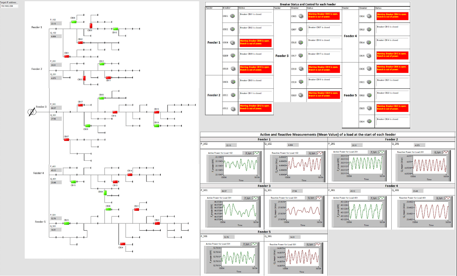
Hardware-in-the-loop testing couples a real-time simulator with the exact electronic controller, relay, or power module slated for field deployment. The simulator calculates electromagnetic transient (EMT) or phasor‑domain behavior at microsecond time steps, sending voltage and current signals to the device under test while receiving its responses. This closed loop reveals control logic flaws, timing bottlenecks, and protection misoperations long before site commissioning. You gain quantitative evidence that software and hardware cooperate correctly under both routine and faulted grid states, trimming costly field rework and outage risk.


Benefits of Hardware-in-the-Loop Testing Across Power System Projects 


Hardware-in-the-loop testing delivers clear business and engineering benefits across transmission, distribution, and inverter-based resource applications. It verifies microsecond timing, captures hidden interactions, and supports continuous improvement throughout the asset life cycle.

  • Cost containment for high‑power trials: Large‑scale faults and overcurrent events play out digitally, eliminating rental fees for load banks or rotating machines.
  • Faster controller iteration: Engineers load new firmware to the device under test, rerun identical scenarios, and compare results within hours instead of waiting for grid study windows.
  • Grid modernization risk mitigation: Advanced protection schemes, synthetic inertia, and grid‑forming modes face realistic disturbances without jeopardizing service continuity.
  • Scalability for distributed energy resources: A single test bench can represent thousands of rooftop inverters or electric vehicle chargers, helping planners quantify hosting capacity.
  • Compliance confidence: Standards such as IEEE 1547.9 and IEC 61850 performance are proven under witness conditions, smoothing regulatory approval.
  • Improved stakeholder alignment: Quantitative dashboards and repeatable results foster shared confidence among utilities, vendors, and regulators.

“Hardware-in-the-loop testing couples a real‑time simulator with the exact electronic controller, relay, or power module slated for field deployment.”


Hardware-in-the-loop testing consistently delivers these benefits for microgrids, utility substations, and renewable power plants. The technique replaces guesswork with measurable evidence that devices will hold stable during real‑time disturbance events. Its repeatability and transparency shorten approval cycles, reduce capital expenditure, and raise confidence across the project team.
When to Use a Hardware-in-the-Loop Test Bench for Power Systems 


Hardware-in-the-loop test benches prove most valuable at specific project milestones and for particular study objectives. Selecting the right moment maximizes engineering impact and protects budget allocations. Teams that time adoption well report smoother rollouts and fewer commissioning surprises.

Early‑Stage Controller Prototyping


Prototyping benefits when firmware logic evolves weekly yet lab hardware remains limited. A simulator acts as the “rest of the grid,” feeding the controller new waveforms as algorithms mature. Engineers catch PWM saturation, numeric overflows, and pointer errors under high‑frequency switching without blowing fuses. The bench grows with model complexity while preserving previous test cases for regression.

Protection Scheme Validation


Differential, distance, and directional protection must trip within tightly defined windows. Replaying evolving fault libraries exposes scheme sensitivity to CT saturation or communication latency. Hardware-in-the-loop testing measures pickups and clears down to the microsecond, ensuring coordination across multiple relays. This scrutiny prevents nuisance trips that would erode service quality.

Microgrid Stability Studies


Isolated or islanded networks experience large frequency excursions when a feeder drops. A test bench applies load steps, renewable variability, and motor starts to confirm that droop, virtual inertia, and ride‑through parameters arrest frequency quickly. Pass–fail metrics emerge without energizing an actual switchgear lineup. Operators gain evidence that autonomous controls maintain stability during utility outages.

Converter Compliance Checks


Grid codes demand specific harmonic limits, flicker rates, and fault‑ride‑through envelopes. Power converters under test connect to a simulated transmission model that feeds phase jumps, low‑voltage dips, and frequency sweeps. Engineers verify that active current injection and voltage support stay within limits. The process avoids shipping a megawatt‑scale prototype to an off‑site test laboratory.

Training and Skill Building


Lab personnel learn to diagnose oscillations or protection misoperations using the exact instruments found at live substations. A test bench pauses, rewinds, and replays fault records, fostering deeper intuition than passive study. Operators practice restoration sequences safely, boosting preparedness for genuine events.

Hardware-in-the-loop test benches serve throughout concept, design, and maintenance phases when precise, repeatable disturbance exposure is required. Deploying the bench at these moments lowers technical risk, clarifies hand‑offs between disciplines, and safeguards grid reliability.


How to Set Up a Scalable Hardware-in-the-Loop Test Strategy 


Building a sustainable hardware-in-the-loop test strategy involves making technical choices and ensuring organizational alignment. An iterative, metric‑driven roadmap ensures the bench keeps pace with project scope. Internal champions who focus on measurable outcomes will secure long‑term value.

Define Clear Objectives


Start with quantifiable questions, such as fault‑ride‑through grading or PWM loss‑of‑modulation limits. Objectives guide model fidelity, channel count, and data logging depth. Clear goals prevent over‑engineering the bench while guaranteeing decisive evidence. Stakeholders approve budget faster when desired outputs are explicit.

Model Fidelity Selection


Electromagnetic transient solvers capture microsecond behavior, phasor solvers suit slower interactions, and combined methods address multi‑rate systems. Selecting fidelity per study avoids unnecessary computational load. Model accuracy must match hardware sampling rates so that numerical aliasing never hides instability. Continuous verification against field records maintains credibility.

Hardware Partitioning


Assign I/O cards, signal conditioners, and amplifiers according to voltage, current, and bandwidth needs. Digital signals for status words can share a backplane, while analog channels with kilohertz content require isolation. Proper partitioning protects sensitive circuits and avoids crosstalk. Modular racks simplify expansion as new devices arrive.

Automation and CI Integration


Continuous integration frameworks run nightly regressions on the latest firmware to catch performance drifts early. Scripting interfaces schedule test suites, collect data, and push results to dashboards. Automated workflows cut manual labor and support agile firmware releases. Version control assures identical conditions for every rerun.

Metrics and Reporting


Raw waveforms hold little meaning without digestible insights. KPIs such as peak overshoot, trip time, and total harmonic distortion link bench data to grid performance. Reports export directly into project documentation, supplying auditors with traceable evidence. Consistent metrics allow year‑over‑year benchmarking as regulations tighten.

A scalable hardware-in-the-loop test plan aligns technical depth with business objectives, grows through modular additions, and embeds automation for continuous insight. Teams that adopt this structured approach document faster approval cycles, reduced field failures, and stronger collaboration between hardware and software disciplines.


Comparing Hardware-in-the-Loop and Software-in-the-Loop for Power Applications 


The main difference between hardware-in-the-loop testing and software-in-the-loop lies in the presence of physical equipment inside the control loop. Software-in-the-loop runs the controller code on the same computer as the grid model, ideal for algorithm development when I/O timing is less critical. Hardware-in-the-loop inserts the actual processor board or relay, capturing latencies, quantization, and sensor dynamics that models alone cannot reproduce. Teams often start with software-in-the-loop to debug logic, then move to hardware-in-the-loop for final performance proof.

“A scalable hardware-in-the-loop test plan aligns technical depth with business objectives, grows through modular additions, and embeds automation for continuous insight.”


Aspect

Software-in-the-Loop (SIL)

Hardware-in-the-Loop (HIL)

Physical Hardware

None

Real controller, relay, or converter

Time Step

Flexible, often slower than real time

Strictly real‑time, microsecond range

Purpose

Algorithm development, unit tests

System validation, compliance proof

Risk Exposure

Zero hardware damage risk

Low, limited to lab equipment

Setup Cost

Lowest

Moderate, includes I/O and amplifiers

Fidelity

Limited by code abstraction

Includes sensor noise, quantization, latency

Typical Stage

Early design

Pre‑commissioning, regression, operator training

Combining both methods yields a tiered validation pipeline. Engineers fine‑tune algorithms in SIL, migrate to HIL for physical insight, and enter field trials only after the bench shows acceptable margins.

Common Challenges in Hardware-in-the-Loop Testing for Engineers 


Hardware-in-the-loop testing introduces practical hurdles that require structured mitigation. Anticipating these obstacles prevents schedule slips and maintains data integrity. Addressing each challenge methodically keeps the bench delivering value across multiple programs.

Signal Latency


Even microsecond delays distort closed‑loop behavior at high switching frequencies. Selecting I/O modules with deterministic paths and synchronized clocks curtails phase errors. Engineers should measure end‑to‑end latency with loopback tests before critical studies begin. Continuous monitoring alerts staff when firmware updates alter timing budgets.

Model‑Hardware Synchronization


The simulator and device under test must share a common time base. Unsynchronized clocks lead to drift, misaligned sampling, and false trip assertions. Precision time protocol (PTP) or GPS can lock subsystems to nanosecond accuracy. Periodic health checks ensure synchronization holds after network maintenance.
Sensor Calibration


Voltage dividers, shunts, and fiber‑optic transducers introduce gain and offset that skew results. A yearly calibration plan compares bench readings against laboratory standards. Automated routines adjust scaling factors in the data acquisition firmware. Proper calibration protects against misinterpreting apparent controller errors.

Data Management


Continuous high‑resolution logging strains storage systems and complicates analysis. Engineers should define rolling buffers, triggered captures, and summary statistics to focus on events of interest. File naming conventions and metadata tagging support traceability across tests. Cloud archiving with access controls balances availability and security.

Change Management


Multiple engineers editing models, firmware, and scripts risk configuration drift. Version control repositories track every modification and enable rollbacks. Pull requests with peer review catch errors before they reach hardware. Structured change management maintains bench stability while supporting agile workflows.

Challenges in hardware-in-the-loop testing seldom disappear entirely, yet organized procedures reduce their impact. Teams that adopt latency measurement, time synchronization, calibration, disciplined data handling, and version control maintain trust in every result. Such rigor preserves schedule confidence and upholds regulatory compliance.


How OPAL‑RT Supports Hardware-in-the-Loop Testing for Power Systems 


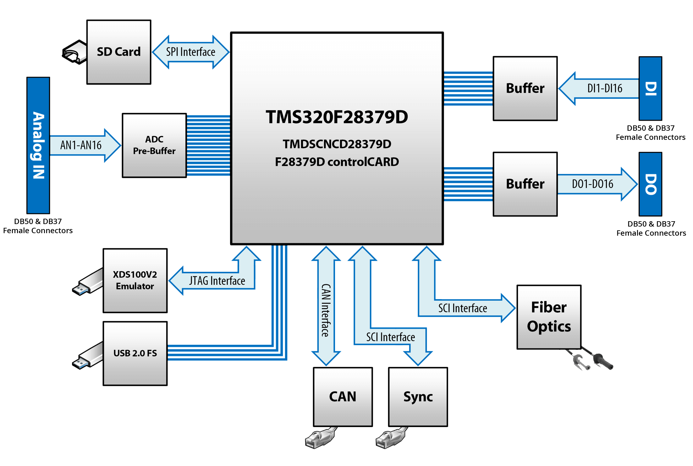
OPAL‑RT products combine real‑time simulators, flexible I/O, and intuitive software so power engineers can run hardware-in-the-loop testing without sacrificing precision or budget. Ultra‑low‑latency FPGA and CPU architectures process EMT networks at sub‑20 µs steps, feeding amplifiers or low‑level digital links straight into relays, converters, or plant controllers. Open APIs connect with MATLAB / Simulink, Modelica, Python, and FMI standards, allowing existing models to execute unmodified while scaling channel counts to thousands. Global support, field‑proven reference libraries, and turnkey synchronization solutions remove setup guesswork, letting your team focus on engineering insight rather than infrastructure maintenance.

Engineers and innovators around the world are turning to real‑time simulation to accelerate development, reduce risk, and push the boundaries of what is possible. At OPAL‑RT, we bring decades of expertise and a passion for innovation to deliver the most open, scalable, and high‑performance simulation solutions in the industry. From hardware-in-the-loop testing to AI-enabled cloud simulation, our platforms empower you to design, test, and validate with confidence.

Common Questions About Hardware in the Loop Testing for Power Systems

Hardware-in-the-loop testing connects a real‑time simulator with physical controllers or converters, letting you expose the hardware to precise voltage and current waveforms while monitoring its responses under safe laboratory conditions.


Utilities gain earlier fault detection, shorter commissioning schedules, and quantified compliance evidence, all while avoiding field outages and costly load banks.


A hardware-in-the-loop test bench updates grid models at microsecond resolution and closes the loop with the device under test, whereas traditional labs rely on static sources or offline calculations that miss timing‑dependent issues.


Transition once control logic functions correctly in simulation and firmware is stable, so physical latencies, sensor dynamics, and I/O limits can be examined before site deployment.


Select modular simulators, implement time‑synchronized I/O expansion, and embed automated regression scripts so additional feeders, DERs, or protection zones can be added without re‑architecting the bench.