• 0Shopping Cart
OPAL-RT
  • SOLUTIONS
    • Aerospace
      • Aerospace Overview
      • eVTOL
      • More Electric Aircraft
      • Onboard Power Systems
    • Automotive
      • Automotive Overview
      • Battery Management Systems
      • Electric Vehicle
      • Automotive Powertrain Emulation
    • Autonomous Vehicle / ADAS
    • Power Electronics
      • Power Electronics Overview
      • Energy Conversion Controls
      • Hybrid and Electrical Transportation
    • Power Systems
      • Power Systems Overview
      • Cybersecurity
      • Digital Twins
      • Distribution Automation
      • Microgrid
      • Modular Multilevel Converter
      • Power Generation
      • Power System Controls
      • Protection Systems
      • Substation Automation | IEC 61850
      • Wide Area Monitoring Protection and Control
    • Academic Solutions
      • Education
      • Research
    • Type of Simulation
      • Hardware-in-the-Loop (HIL)
      • Power hardware-in-the-loop (PHIL)
      • Rapid Control Prototyping (RCP)
      • Software-in-the-Loop (SIL)
      • Simulation Acceleration
  • PRODUCTS & SERVICES
    • Software Platforms
      • Software Platforms Overview
      • RT-LAB Multi-Domain - Simulink-Based
      • HYPERSIM Power Systems
      • NI VeriStand Automotive
    • Software Toolboxes
      • ARTEMiS CPU-based Electrical
      • eHS FPGA-based Power Electronics
      • ePHASORSIM Electro-Mechanical Phasor
      • Orchestra Co-Simulation
      • RT-XSG FPGA-based I/O and Comm
      • TestView Test Automation
      • ScopeView Graph & Data Processing
    • Software Bundles
      • Software Bundles Overview
      • eMEGASIM
      • eFPGASIM
    • Hardware Platforms
      • Hardware Platforms Overview
      • OP4512 Compact Entry-Level
      • OP4610XG Compact Mid-Range
      • OP5705XG Versatile
      • OP5707XG High-End Performance
      • OP5033XG Real-Time Computer
      • OP8666 RCP Controller
    • Hardware Components
      • I/O and Communication Interfaces
      • 4-Quadrant Power Amplifier
      • SLSC Modules
      • Communication Protocols
      • FPGA and I/O Expansion Units
      • Power and Control
      • Conditioning and Monitoring
      • Accessories
    • Specialized Simulator
      • Microgrid PHIL Test Bench
      • MMC Test Bench
      • Power Electronics Test Bench
      • Educational Lab Kits
      • BERTA Test Bench
    • Services
      • Integration
      • Expert Services & Consulting
      • OPAL-RT Training
    • OPAL-RT Product News
  • SUPPORT
    • Resource Center
    • Download Center
    • Support Center
      • Support Center
      • Contact Technical Support
      • Knowledge Base
      • Online Learning Platform
      • User Documentation
  • COMPANY
    • Events
    • Company Profile
    • Customers
    • Leadership
    • Partners
    • News
    • Careers
  • CONTACT
    • Find your Local Contact
    • Contact Us
    • Contact Technical Support
    • Give us your Feedback
  • STORE
    • en
      • Français
      • 简体中文
      • Deutsch
  • Search...
  • ham
    • en
      • Français
      • 简体中文
      • Deutsch
  • Search...
OPAL-RT
  • SOLUTIONS
    Aerospace
    Aerospace Overview
    eVTOL
    More Electric Aircraft
    Onboard Power Systems
    Automotive
    Automotive Overview
    Battery Management Systems
    Electric Vehicle
    Automotive Powertrain Emulation
    Autonomous Vehicle / ADAS
    Power Electronics
    Power Electronics Overview
    Energy Conversion Controls
    Hybrid and Electrical Transportation
    Power Systems
    Power Systems Overview
    Cybersecurity
    Digital Twins
    Distribution Automation
    Microgrid
    Modular Multilevel Converter
    Power Generation
    Power System Controls
    Protection Systems
    Substation Automation | IEC 61850
    Wide Area Monitoring Protection and Control
    Academic Solutions
    Education
    Research
    Type of Simulation
    Hardware-in-the-Loop (HIL)
    Power hardware-in-the-loop (PHIL)
    Rapid Control Prototyping (RCP)
    Software-in-the-Loop (SIL)
    Simulation Acceleration
  • PRODUCTS & SERVICES
    Software Platforms
    Software Platforms Overview
    RT-LAB
    HYPERSIM
    NI VeriStand
    Software Toolboxes
    ARTEMiS
    eHS
    ePHASORSIM
    Orchestra
    RT-XSG
    TestView
    ScopeView
    Software Bundles
    Software Bundles Overview
    eMEGASIM
    eFPGASIM
    Hardware Platforms
    Hardware Platforms Overview
    OP4512
    OP4610XG
    OP5705XG
    OP5707XG
    OP5033XG
    OP8666
    Hardware Components
    I/O and Communication Interfaces
    4-Quadrant Power Amplifier
    SLSC Modules
    Communication Protocols
    FPGA and I/O Expansion Units
    Power and Control
    Conditioning and Monitoring
    Accessories
    Specialized Simulator
    Microgrid PHIL Test Bench
    MMC Test Bench
    Power Electronics Test Bench
    Educational Lab Kits
    BERTA Test Bench
    Services
    Integration
    Expert Services & Consulting
    OPAL-RT Training
    OPAL-RT Product News
  • SUPPORT
    Resource Center
    Download Center
    Support Center
    Support Center
    Contact Technical Support
    Knowledge Base
    Online Learning Platform
    User Documentation
  • COMPANY
    Events
    Company Profile
    Customers
    Leadership
    Partners
    News
    Careers
  • CONTACT
    Find your Local Contact
    Contact Us
    Contact Technical Support
    Give us your Feedback
  • STORE
    • en
      • Français
      • 简体中文
      • Deutsch
  • Search...

In order to access this page, please sign in below.

Forgot your Login info?

Not registered yet? Get an OPAL-RT Account

Thank you for joining the SheSavvy Community

Terms and Conditions of Sales

You are here: Home1 / Terms and Conditions of Sales

Terms and Conditions of Sales

As stated herein, ‘Seller’’ is OPAL-RT Technologies Inc. and the ‘’Buyer’’ is the recipient of the quotation and issuer of the purchase order. The following Terms and Conditions of sales (the ‘’Contract’’) apply to the Seller’s quotations and any sales that results.

1. GENERAL

1.1 Quotations are offered for acceptance within thirty (30) days unless a longer time is specified on the face of the quotation, and if not so accepted within the designated period shall be deemed withdrawn.

1.2 All purchase orders are subject to this Contract.

1.3 In this Contract, the expression “Goods” relates to the goods and services, which the Seller proposes to sell or has sold to the Buyer, being the Goods described in the Seller’s Quotation and a reference to Goods includes services and electronic products of any kind.


2. ACCEPTANCE OF QUOTATION AND PURCHASE ORDERS

2.1 The quotation must be accepted by the Buyer in writing by counter-signature of the quotation for any quotation above $100,000 US and by electronic confirmation to the Seller for the others.

2.2 Seller’s acceptance of any purchase order is contingent upon Seller’s approval of Buyer’s credit.

2.3 Acceptance of the Buyer’s purchase orders by the Seller does not constitute acceptance of the Buyers’ terms and conditions of sale quoted therein, unless specifically authorized with the written consent by the Seller. In the event of the lack of enforcement of the Seller’s terms and conditions of sale by the Seller or by the agent of the Seller or by the Seller’s subsidiary, neither waiver of the Seller’s terms and condition of sales, nor the Seller’s acceptance of Buyer’s conditions of purchase is to be deemed or implied. In any event, if the Buyer fails to notify the Seller in writing within ten (10) days of the Seller’s order acknowledgement that any terms or conditions of that order are unacceptable to the Buyer, the Buyer shall be deemed to have accepted the Contract as set forth in the acknowledgement. Upon acceptance in this manner, the Contract cannot be canceled, revoked, or modified in any particular without the specific written consent of the Seller, after appropriate provision for payment by the Buyer for any additional costs and expenses resulting from such changes.


3. CERTIFICATION STANDARDS, GOODS MARKINGS

3.1 Seller represents and warrants that all Goods purchased by the Buyer shall be conform with all applicable laws related to product safety, electromagnetic compatibility, low voltage equipment, radio equipment and wireless, and restriction of hazardous substances. Seller, or Seller’s agent, will affix the applicable regulatory mark on Goods as required.

3.2 Unless otherwise agreed to in a SOW or a Quotation, when required by local regulation, Buyer shall have the responsibility for assisting Seller or Seller’s agent in all on site testing or action required to respect certification standards or Goods marking, notably permitting access to the Goods and Buyer’s premises and by fully collaborating in obtaining and maintaining applicable certifications and markings for the Goods.


4. DELIVERY

4.1 All delivery dates quoted are estimated, are not guaranteed and do not form a term of this Contract. The Seller undertakes to make every endeavor to adhere to the delivery schedule but will not accept cancellation of Contract for, or liability for, any direct or indirect losses which may arise from late delivery.

4.2 Unless otherwise agreed in writing by the Seller, all costs of delivery will be for the Buyer’s account.

4.3 The Seller is not and will not be liable for any loss or damage however it arises because of any failure to deliver or delay in delivery for any reason including, without limitation:

4.3.1 Acts of God, fire, lightning ,explosion, or flood; lock-out, strike or other labor difficulty;
4.3.2shortage or unavailability of raw materials, labor, power supplies or transport facilities; or failure or inability to obtain licenses or the effect of any applicable laws, orders, rules or regulations of any government or competent authority
4.3.3 Breakage, accident or other damage to or failure of machinery or equipment.


5. DAMAGE OR LOSS IN TRANSIT

5.1 All Goods are delivered EXW Montreal except if shipping fees are added into the quote then the incoterm CPT Buyer’s premises will apply. Seller accepts no responsibility past the Buyer’s facility for damage or loss of Goods in transit. Any such damage should be noted on the carriers paperwork and notified to the Seller within four days of receipt and the Goods held for inspection to enable a claim to be made on the carrier. If the Goods are lost or not received by the Buyer within six days of invoice, the Seller should be immediately notified.

5.2 In particular, at the time of delivery, the Buyer should verify the condition of the tape used for packaging of goods shipped, and notify the Seller of any issue at https://www.opal-rt.com/contact-technical-support/ . Failure to report any damage to the sealing tape of the shipped Goods will result in the Buyer being held responsible for all cost of damages.

5.3 The Buyer shall familiarize himself with best practices for user and machine safety, as well as important notes and warnings specific to OPAL-RT installations. These are in addition to, and do not replace, all other generic and specific safety information provided, and can be found at:
General safety warnings https://wiki.opal-rt.com/pages/viewpage.action?pageId=28508726
Uncrating a large hardware platform instructions https://wiki.opal-rt.com/display/HDGD/Uncrating+a+Large+OPAL-RT+Hardware+Product.


6. PRICE AND QUOTATION

6.1 Unless otherwise agreed to in writing by the Seller, all quotations expire 30 days from the date of the quotation. Prices are thereafter subject to change without notice and Goods will be invoiced at the price ruling at the date of dispatch.

6.2 All Goods will be charged at the prices ruling at the date of order plus any applicable Goods and Services Tax (GST) which must be paid to the Seller by the Buyer when payment for the Goods is due.

6.3 Prices will be rounded to the nearest whole cent in the Seller’s invoices.

6.4 When preparing a quote, the Seller uses its best knowledge to estimate the necessary time for training, commissioning or giving expert services. If it happens that more time is necessary to complete the work, then the Seller will charge the Buyer all overtime hours at 1,25 X the regular rate.

6.5The Buyer will have one (1) year from the delivery date to request and use such Seller’s commissioning, training or expert services. After this delay, the Seller shall not be obligated to perform such commissioning, training or expert services and will be entitled to execute payment, as per the quotation.


7. TERMS OF PAYMENT

7.1 For orders including software only, payment must be made in cash without deduction within 30 days of the date of invoice or by letter of credit approved by the Seller, unless otherwise provided in the Seller’s Quotation or agreed in writing by the Seller or specified by the Seller at the time an order is received.

7.2 For orders including Seller’s hardware or third party software or hardware, Seller will invoice Buyer immediately after reception of the purchase order and payment is due no later than 30 days after purchase order date through bank wire transfer. The Buyer understands that the Seller will not be able to deliver any systems unless the hardware and third party software have been fully paid.

7.3 For Seller’s distributors, payment must be made according to distributorship agreement.

7.4 The Seller reserves the right to vary the terms of payment and to require payment in cash in full prior to delivery if, at any time, the credit worthiness of the Buyer is, in the Seller’s opinion, unsatisfactory. If the Buyer has not paid the Seller in full within 30 days of the payment being due, the Seller may, at its option, rescind the Contract and resell or dispose of the Goods without prejudice to any claims for damages against the Buyer.

7.5 Payment of invoices must be received not later than 30 days from the date of invoice, thereafter the Seller reserves the right to charge interest at the rate of 1% per month or part thereof for outstanding amounts owing by the Buyer.

7.6 Where payment is not received by the Seller within 30 days from the date of invoice, the Seller may in its absolute discretion:

a) Withhold further supply, activate software time locks and dispose of stock held for the order.
b) Institute legal action for recovery of outstanding balance plus interest and costs incurred, including legal costs; and
c) Require the Buyer to pay cash on delivery for any further Goods, and
d) The Seller shall not be liable to the Buyer for any loss or damage resulting directly or indirectly from such action.


8. CHANGES AND CANCELLATION

8.1 If the Buyer makes a change to an order causing a delivery delay or cancels an order less than thirty (30) days prior to scheduled shipment, Buyer shall pay to the Seller a fee equal to 5% of the list price of any Goods affected.

8.2 In addition, where any such change causes a delay in delivery of any Goods affected of greater than one (1) month from the proposed date of delivery for the Buyer’s original order, the Buyer will be charged an extra 1% per month of the purchase order until final delivery.

8.3 If the Buyer cancels an order for any Goods not included in the Seller’s current price list, any time after the order is received by the Seller then the Buyer will be subject to that additional charge.

8.4 If the Buyer cancels any order or refuses to accept all or any of the Goods in an order other than in circumstances permitted in these Conditions, the Buyer will be liable for any resulting damage or loss suffered by the Seller. If the Goods have been or are in the process of being manufactured or produced specifically for the Buyer, the Buyer will pay to the Seller as liquidated damages the full Contract price of the Goods and any costs incurred by the Seller (including, but without limitation, any GST) less the current scrap value of the Goods as determined by the Seller.


9. LIABILITY

9.1 LIMITED LIABILITY : UNLESS OTHERWISE PROVIDED FOR IN THIS CONTACT, UNDER NO CIRCUMSTANCES WILL THE SELLER OR ITS SUB-CONTRACTORS OR SUPPLIERS BE LIABLE TOWARDS THE BUYER OR ANY THIRD PARTY FOR ANY, INDIRECT, SPECIAL, INCIDENTAL, PUNITIVE OR EXEMPLARY DAMAGES, OR CLAIMS OR COSTS OF ANY KIND INCLUDING, WITHOUT LIMITATION, ANY LOSS OF PROFITS OR OTHER ECONOMIC LOSS (RESULTING FROM A CONTRACTUAL OR EXTRA-CONTRACTUAL FAULT OR FROM NEGLIGENCE), ARISING OUT OF RELATED TO THE GOODS, EVEN IF THE SELLER HAS BEEN NOTIFIED OF THE POSSIBILITY OF SUCH DAMAGES. CERTAIN JURISDICTIONS PROHIBIT THE EXCLUSION OR LIMITATION OF LIABILITY FOR INDIRECT OR CONSEQUENTIAL DAMAGES, AND IT IS POSSIBLE THAT ONE OR MORE OF THE AFOREMENTIONED EXCLUSIONS OR LIMITATIONS WILL NOT APPLY TO THE BUYER. IT IS ALSO POSSIBLE THAT THE BUYER MAY HAVE OTHER RIGHTS, WHICH RIGHTS MAY VARY FROM ONE PLACE TO ANOTHER. UNDER NO CIRCUMSTANCES WILL THE SELLER TOTAL LIABILITY TOWARDS THE BUYER EXCEED THE VALUE OF THE GOODS TO THE BUYER OR THE VALUE OF THE PRODUCT IN DEFECT SUPPLIED BY THE SELLER AND PAID FOR BY THE BUYER

9.2 BUYER INDEMNIFICATION: Except where the damages results from Buyer’s or Buyer’s employees, agents or contractors fault, negligence or willful misconduct, the Seller shall indemnify, defend and hold harmless the Buyer and its affiliates, and their respective directors, officers, employees, insurers, successors and assigns (collectively, the “Buyer’s Indemnified Parties”), from and against any and all liabilities, damages and expenses (including, without limitation, attorneys’ fees and legal costs) that they, or any of them, may sustain or incur as a result of


a) any breach of any representation, warranty or covenant made by Seller in the Contract,


b) any actual or alleged injury to or death of any person, or any actual or alleged damage to or loss of any property, arising out of (i) the manufacturing or the defect of Seller’s Goods, (ii) any Services performed by OPAL-RT or any of its employees, agents, suppliers or contractors, or (iii) the negligent acts or omissions or intentional misconduct of Seller or any of its employees, agents, suppliers or contractors,


c) or otherwise and generally arising out of or having its origin in any act or omission of Seller, its agents, representatives, affiliates or employees in connection with this Contract.


In any case, notwithstanding what precedes, except in the event of willful misconduct or gross negligence on the part of Seller, Seller’s liability toward the Buyer shall not be higher than the value of the Goods sold that lead to the claimed damages.


9.3 SELLER INDEMNIFICATION: The Buyer agrees to indemnify, hold harmless and defend the Seller and its affiliates, and their respective directors, officers, employees, clients, agents, insurers, successors and assigns (collectively, the “Seller’s Indemnified Parties”), from and against any and all liabilities, damages and expenses (including, without limitation, attorneys’ fees and legal costs) that they, or any of them, may sustain or incur as a result of:


a) the negligent acts or omissions or intentional misconduct of Buyer or any of its employees, agents, suppliers or contractors;


b) the migration of the Seller’s Goods to a different hardware or software environment;


c) unlawful or unauthorized third-party hacking into the Buyer’s computer equipment;


d) any infringement of Seller’s Intellectual Property;


e) any breach of any representation, warranty or covenant made by Buyer in the Contract.


10. FORCE MAJEURE EVENTS

10.1 Neither Party shall be liable for any delay in the performance of its obligations hereunder due to an adverse event caused by a superior force as awarded by a competent authority or court of law (hereinafter referred to as “Force Majeure

10.2 Seller undertakes to (i) notify Buyer immediately of any event of Force Majeure and (ii) resume its performance forthwith after the Force Majeure event ceases. If any Force Majeure event continues for an unbroken period exceeding thirty (30) days, Buyer is entitled by notice in writing to the Seller to terminate this Contract and any order associated with it. In the event of such notice being given, all Services completed and accepted hereunder before the giving of such notice, and all Services completed and accepted thereafter in accordance with and to the extent specified in such notice, shall be paid for by Buyer subject to acceptance by Buyer. In no case under such termination shall Seller be entitled to any amount which taken together with any amounts paid or due to Seller under the terminated order, would exceed the total amount payable for the Services to be supplied under the terminated order.


11. INTELLECTUAL PROPERTY

11.1 For the purpose of this Contract, the term “Intellectual Property” means

(a) all inventions (whether or not patentable or reduced to practice), all improvements thereto, and all patents and industrial designs (including utility model rights, design rights and industrial property rights), patent and industrial design applications, and patent disclosures;


(b) all trademarks, service marks, designs, trade dress, logos, slogans, and all other indicia of origin, and all goodwill associated with any of the foregoing;


(c) all works of authorship (whether or not copyrightable), copyrights (including “look-and-feel”), mask works, database rights and moral rights;


(d) all trade secrets, know-how, technologies, processes, techniques, protocols, methods, formulae, recipes, product specifications, data, scents, initials, algorithms, compositions, industrial models, architectures, layouts, designs, drawings, plans, Specifications, methodologies, ideas, research and development, and confidential information (including technical data, customer and supplier lists, pricing and cost information, and business and marketing plans and proposals);


(e) all software; and


(f) all other proprietary and intellectual property rights worldwide.


11.2. Trademarks, know-how, computer programs, software and other Intellectual Property rights belong to Seller and shall remain Seller´s sole property and Seller shall as far as reasonably protect such rights. Nothing contained in this Contract shall be construed to give the Buyer any proprietary interest in or rights to Seller´s Intellectual Property, and all use by the Buyer of Seller’s trademarks and symbols shall be to the benefit of Seller. 

11.3. The sale and purchase of the Goods does not confer on the Buyer any of Seller’s Intellectual Property rights. Nothing in this Contract is intended, nor shall anything in this Contract be construed to grant or convey any Intellectual Property rights of Seller to Buyer.

11.4.The Buyer agrees to inform Seller of any known infringement or known alleged infringement of industrial, commercial or Intellectual Property rights, belonging to Seller, or any legal action taken against the Buyer in respect of the breach of such rights. The Buyer shall safeguard Seller ´s interests by making information on such infringement to Seller immediately available.

11.5. Seller grants to the Buyer a limited, non-exclusive, non-transferable, royalty-free, worldwide right and license to Seller’s Intellectual Property necessary for Seller’s unrestricted use and support of the Goods provided under the Contract. This license does not confer to Buyer any right to copy and reproduce, alter or otherwise moditfy Seller’s Intellectual Property.


12. RETURN POLICY

12.1 The Seller warrants to the original Buyer and/or ultimate Buyer of the Seller’s Goods that if any part thereof proves to be defective in material or workmanship within one (1) year after the delivery of the invoice, such defective part will be repaired or replaced, free of charge, at the Seller’s discretion, if shipped prepaid to Opal-RT Technologies Inc. at 1751 Richardson, suite 1060, Montreal, Quebec, Canada, H3K 3G6, in a package equal to or in the original container. The Goods will be returned freight prepaid and repaired or replaced if it is determined by the Seller that the part failed due to defective materials or workmanship. Otherwise, the fees will be charged to the Buyer (see Warranty Policy and Liability on Opal-RT’s web site at opal-rt.com , under Support, Return Merchandise, click on “Please read about our RMA procedure and warranty policy”). The repair or replacement of any such defective part shall be the Seller’s sole and exclusive responsibility and liability under this limited warranty.


13. PREVAILING CONTRACT

13.1 These terms and conditions supersede all previous or different instruments, namely Buyer’s purchase order’s terms if any, unless otherwise provided by law, and no change or modification of these terms and conditions shall be of any force unless such change or modification shall be executed by an authorized officer of Seller. The terms and conditions of this instrument shall supersede any terms and conditions on any confirmation purchase orders or other documents Buyer may present, the terms and conditions herein being binding. Acceptance of any quotation is limited to the terms and conditions herein.


14. GOVERNING LAWS

14.1 This Contract created by Seller’s quotation, Buyer’s purchase order and Seller’s acknowledgement shall be governed by and construed in accordance with the laws of the province of Québec and the laws of Canada applicable herein.


15. LANGUAGE

15.1 The parties hereto confirm that it is their express wish that this Agreement be drawn up in English only. Les parties aux présentes confirment leur volonté expresse que la présente convention soit rédigée en anglais seulement.

Download PDF Version
V13 | August 03, 2022


Popular Resources

  • Rapid Control Prototyping
  • Hardware-in-the-loop
  • Cybersecurity
  • Microgrid HIL Real-Time Simulation

Discover

  • HYPERSIM
  • RT-LAB
  • OP5707XG
  • Turnkey Test Benches

CONNECT WITH US

  • Contact Us
  • Contact Technical Support
  • Events

FOLLOW OPAL-RT

Opal-RTLinkedIn
Opal-RTFacebook
Opal-RTTwitter
Opal-RTYouTube
© 2022 - OPAL-RT TECHNOLOGIES, Inc.         Privacy Policy | Legal Notice
Scroll to top
OP205: Power Electronics Real-Time Simulation with eHS

This course is intended for professionals who want to simulate power electronic circuits with our FPGA-based solver: eHS. This toolbox provides the flexibility and speed required for very fast power conversion applications for HIL simulation.

Prerequisites :
• OP-101 : RT-LAB – Real-Time Simulation Systems Fundamentals

GOALS:
– Learn how to run power electronic circuits in real-time for HIL applications
– Take advantage of FPGA high performance for solving power electronic circuits in real-time
– Learn how to design your power electronic circuits with the OPAL-RT Schematic Editor
– Learn how to implement a control algorithm on CPU for your power electronic circuits
– Learn how to interface your power electronic circuits design with external controller
– Learn how to simulate faults on power electronic converter circuits

Request Training

OP101: RT-LAB - Real-Time Simulation Systems Fundamentals

This course introduces OPAL-RT systems and applications using RT-LAB. This course is a prerequisite for eMEGASIM, eFPGASIM, and ePHASORSIM. RT-LAB is used in a variety of domains, including power systems, power electronics, automotive applications, aerospace, mechatronics and more.

Prerequisites:
• Basic knowledge of Matlab®/Simulink®

GOALS:
– Learn the fundamentals of real-time simulation
– Get started with RT-LAB Software
– Understand when and how to use distributed and parallel real-time simulation
– Connect models with I/Os


Request Training

OP203: ARTEMiS - Power Systems Real-Time Simulation

This course is intended for professionals who want to simulate power systems with ARTEMiS by converting their Simulink‘s SimPowerSystems™ based model into a complete HIL system.

Prerequisites:
• OP-101: RT-LAB – Real-Time Simulation Systems Fundamentals

GOALS:
– Learn how to run power systems models in real-time for HIL applications
– Take advantage of dedicated toolboxes for real-time simulation of power systems and power electronics
– Understand Artemis-SSN, State-Space Nodal solver, as well as its applications
– Learn how to improve the real-time simulation switching results with RT-EVENTS
– Learn how to adapt your SimPowerSystems model for real-time simulation

Request Training

Genesis Alvarez

Abstract

As the complexity of today’s power system increases, it is crucial to have a system protection training program that can incorporate evolving changes and mimics a realistic environment. Dominion Energy is developing real-time models to conduct closed-loop tests. The Substation Automated Training Simulator (SATS) infrastructure is composed of a OP5700 simulator, four OP5600 expansion boxes, and 24 Omicron Power Amplifiers, all mounted on five equipment panels. This system is hardwired to protective relay equipment panels and to primary equipment. There are a variety of use cases that can introduce various abnormal scenarios that may be encountered in a real power system. This closed-loop system enables a simulation to seamlessly replicate the power system response while switching primary substation equipment. Beyond that, it also provides a method of validating entire protection schemes including equipment wiring, individual protective relay settings, and overall device coordination.

OP204: Electro-Mechanical Real-Time Simulation with ePHASORsim

This course is intended for new ePHASORsim users who want to learn Phasor Domain real-time simulation. ePHASORsim simulates electro-mechanical transient stability phenomena of very large power grids with thousands of buses, generators, transformers, transmission lines, loads and controllers.

Prerequisites:
• OP-101: RT-LAB – Real-Time Simulation Systems Fundamentals

GOALS:
– Understand the concept of Phasor Domain simulation features, benefits and limitations
– Import PSS/E, DIgSILENT or other model-based design tools into ePHASORsim
– Connect I/Os and communication buses with ePHASORsim
– Learn about the interaction of ePHASORsim and RT-LAB


Request Training

OP205: Power Electronics Real-Time Simulation with eHS

This course is intended for power electronics and control engineers who want to perform fast power electronics real-time simulation using the combined power of FPGA and OPAL-RT’s unique dedicated solver eHS.

Prerequisites:
• OP-101: RT-LAB – Real-Time Simulation Systems Fundamentals

GOALS:
– Discover the features, flexibility and limitations of FPGA for power electronics real-time simulation
– Understand the overall architecture of real-time simulator between processors and FPGA
– Experience first-hand power electronics real-time FPGA applications using eHS solver

Request Training

OP103: Introduction to Power Electronics Real-Time Simulation with OPAL-RT Add-On for NI VeriStand

This course covers the configuration of a real-time system using the OPAL-RT Power Electronics Add-On for NI VeriStand on the National Instruments hardware platform.


Goals:
– Learn the fundamentals of real-time simulation
– Review the basics of NI VeriStand and the NI hardware platforms
– Understand FPGA-based simulation of power electronics using the eHS solver

Request Training

OP102 - HYPERSIM - Introduction to Power Systems Real-Time Simulation

This course teaches the basics of the HYPERSIM® real-time simulation software platform and its operating principles.

GOALS:
– Understand the operating principles of HYPERSIM®
– Use ScopeView to analyze results
– Build and run a number of control and power system simulation cases showing the capabilities of HYPERSIM®
– Connect models with I/Os


Request Training

Wagner Seizo Hokama

Abstract

We are currently undergoing a major digital transformation in almost all processes of an electricity distribution company. CPFL (www.cpfl.com.br), one of the largest companies in the sector of energy in Brazil, seeks digitalization in all its operational processes, aiming at gains such as cost reduction and increase in the quality and productivity of services.
In line with this corporate strategy, the CPFL group’s Smart Grids engineering management seeks digital technological solutions with the same purpose in its projects. We understand that the complete digitalization of a substation involves the application of the Process Bus (IEC 61850-9-2) for the Substation Protection and Control System (SPCS). The implementation of the Process Bus goes far beyond the economics of removing copper cables from substation ducts. It enables a new horizon of opportunities that a digitalization of signals can offer, such as the implementation of the automation of SPCS operational tests. Substations fully digital could require weeks to test all of its functions, i.e, relay testing is expensive and intelligent choices regarding what we test and how the test must be made. The purpose of this paper is to propose the use of real Real-Time Digital Simulators (RTS), capable of publishing and subscribing GOOSE and Sample Values messages on the Process Bus, to perform operational tests in SPCS. In other words, the idea is present all the benefits achieved when RTS is applied for relay testing in field and not in laboratory environment only.


Historic:

Currently, factory acceptance tests (FAT) are carried out using analog signal injection equipment (secondary current and voltage), one bay at time. It is a very slow and laborious process as they involve the connection and disconnection of several copper cables in the panels, still in the factory. It is also worth noting that because bay-by-bay tests are performed, it is often not possible to evaluate the dynamic behavior of the other bays in the event of a real disturbance due to the lack of modeling of their components and interconnections.


Requirements:

To carry out these tests through the Process Bus, it will be necessary a RTS portable and robust, in order to facilitate its transport for carrying out tests in the factories, where the SPCS panels are assembled, and in the substations, where commissioning, maintenance and troubleshooting are performed. The simulator must also be able to be synchronized by a GPS via PTP (Precision Time Protocol) or similar protocol, publish and subscribe GOOSE and SV messages. The substation modeling capacity will facilitate the execution of operational tests, as well as the SCD file import, as defined by the IEC 61850 standard, arising from the SPCS configuration.


Expected results:

The implementation of the Process Bus in the SPCS will allow the use of digital tools for the injection of current, voltage and binary signals from all the bays of the substation, available on the same bus, without the need to connect any copper cables and power amplifiers.

This facility will enable the automatic generation of sequential and standardized operational tests, aiming at increasing their quality (precision and repeatability) and faster performance, compared to the technique currently used with analog equipment.

In addition, it will be possible to carry out unprecedented tests such as the verification of the dynamic behavior (permanent and transient phenomena) for the entire substation with voltage, frequency and current values, due to the application of the modeling of all electrical equivalents that make up the substation and the power system.

Adekunle Oyenusi

Abstract

Oftentimes, technology is viewed mainly from the perspective of changes that it brings in the lives of people and especially in the ease that is occasioned in its application. Whilst not deviating from this traditional perspective, this Paper goes further to examine the role of real-time simulation in the development of Power Sector of developing economies, especially in Nigeria and the West African Region. The Paper attempts the contribution of Real-time solutions to the development of human capital development whilst at the same time taking a stock of the economic opportunity provided for manufacturers in their incursion into the African markets. It concludes by showing a possible win-win solution for all stakeholders in which the Power Sector records improvement through these technologies while manufacturers build on this business to increase turnover and undertakes researches into new areas.

Ibrahim Elsabrouty

Abstract

Sharing the user story / experience from Maschinenfabrik Reinhausen (MR) with OPAL-RT products in a Modular Multilevel Converter development project, problems, challenges and benefits.

Raphael Mencher

Abstract

The use of DC technology in various applications is increasingly coming to the fore with a view to efficient and sustainable energy supply with the integration of renewable energies and energy storage systems. Besides advantages in improved controllability, system efficiency, and economic feasibility, protection strategies of dc grids are more challenging compared to ac grids due to the missing natural zero crossing of the current. Therefore, specially designed dc circuit breakers or the conception of breaker-less dc grids, using current limiting modulation schemes need to be developed.


As part of the Flexible Electrical Networks (FEN) Medium Voltage Direct Current (MVDC) research grid, a 7 MVA three-phase Dual-Active Bridge (DAB) is built with a nominal voltage of 5 kV. The switching frequency of this converter is 1 kHz, and three single-phase high-frequency transformers provide galvanic isolation and the necessary series inductance. For high power converters in breaker-less dc grids, a fault current limiting control is developed, taking several aspects into account. The most critical factor, thereby, is the small leakage inductance of the converter transformers, resulting in high power dynamics during normal operation and excessive fault currents when the DC link voltage collapses. Another issue is the large minimum turn-on time of the used IGCT semiconductors, which permit the use of conventional modulation schemes.


This presentation shows a control-hardware-in-the-loop simulation to test the actual converter control platform in case of a grid fault. Therefore, the control platform is connected via adapter boards to an Opal-RT OP4510 real-time simulator. One adapter board convert fiber optical signals into electrical while the other one is feeding back measurement signals for the closed loop control. The converter waveforms of the real-time simulation are compared to offline simulation and hardware measurements at 2 KV. Moreover, the fault current limiting modulation in case of pole-to-pole and pole-to-ground fault is implemented on the control platform and tested using the real-time simulation. The results are compared to offline simulation.

Binyu Xiong

Abstract

With the rapid growth of renewable and distributed energy resources (DER), their impact on the legacy AC grid is becoming an important topic. Among integration strategies, the dc microgrid is attractive because of the high efficiency and simple dc interface for various DERs and energy storage devices. When connected to the ac grid, it utilizes a dc-ac converter as the interface. However, there are still many major challenges to integrate dc microgrids in the legacy power system.

  1. Dc-ac converters using traditional power electronics control strategy have fast dynamics. However, the key equipment in power system: the synchronous machine (SM), has slow dynamics with large inertia.
  2. The power generated by DERs is intermittent and will be instantly presented to the grid through fast respondingdc-ac converters. These interactions will lead to frequency, angle, and voltage instability.

Today, the dc-ac converters lack rotational inertia and do not interact with the grid like the SMs.To solve these problems, dc-ac converters mimicking synchronous machinesare proposed. These virtual synchronous machines (VSM) offer several benefits.

  1. A much larger inertia than traditional dc-ac converters is introduced.
  2. Their models are simple hence promising for studying scalability and stability of paralleled VSMs.
  3. The use of phase lock loop (PLL) is eliminated during normal operation, since the VSMs can synchronize with the grid based on the power balance.
  4. Seamless transition from grid-connecting mode to islanding mode and resynchronization back with the grid as a voltage source.

This project proposes a microgrid integration concept to address above mentioned issues. It controls the distributed dc-ac converter as a VSM-based interface (VSM), and includes the following:

  1. A frequency regulation improved but enables the ac frequency and dc voltage being regulated within desired ranges.
  2. An improved dual droop control separately for the VSM and the dc side energy storages to support the VSM functionsand achieve the power management.
  3. An additional power system stabilizer (PSS) to enhance the system stability and energy storages in the dc microgrid into a VSM from the grid point of view.

The digital simulation platforms that use mathematical models of the target systems may not be reliable because some components are usually inaccurate or unavailable. The hardware or field tests eliminate the problems of digital simulation platforms. However, it requires a long setup time, high cost, and application-specific design. These challenges obstruct the extensive utilization of the hardware or field test platforms. These platforms are costly to maintain and difficult to reconfigure. They limit the possibility of conducting the study of the different microgrid scenarios.

To solve these issues, aCHIL platform has been developed based on the OPAL-RT real-time simulators (OP5600/OP5607) and dSPACE MicroLabBox controller (ML1202). The CHIL platform combines the advantages of digital simulation and an external controller. The OP5600 real-time digital simulator at Clean Energy Research Lab in Nanyang Technological University is installed with 12 Intel Xeon E5 processors with a frequency of 3.2 GHz.

Raju Chintakindi

Abstract

With rising global energy demand, transmission lines are operated at their limits, causing electrical gridsto operate under extreme voltage instability conditions. To meet the increased load-demand and the forced tendency across the globe of tilting towards even more renewable generation, solar and windfarms are integrated with increased size and capacity. These uncontrolled natural power injection againmay affect the system’s voltage stability. To avoid blackouts and to achieve the maximum voltagestability of power systems, operators need to do effective real-time grid monitoring and control at loadterminals. Load models are important in the analysis of voltage stability, and accurate load models areuseful in analysing the voltage stability conditions. Phasor-measurement-unit (PMU) based wide-areamonitoring and smart-automation is an innovative technology for measuring load voltage magnitude,phase angle, and frequency variations in a DFIG integrated large wind power system. This researchpaper focuses on estimating the real-time voltage stability through the use of linear, nonlinear, anddynamic load models in presence of a DFIG based wind-farm in WSCC three-machine nine-bus powernetwork using PMU data. This study is carried out using MATLAB-Simulink software.

Mike Mekkanen

Abstract

This work develops Hardware-in-the-loop (HIL) simulation against cyber attacks. The test setup in Opal-EXata cyber attack example ( paper), is based on the software-in-the-loop (CSIL) MGC, however, the hardware-in-the-loop HIL testing is left for the developer. Thus, we design a light-weight intelligent electronic device (IED) that performs MGC, interfaces are developed based on IEC 61850 GOOSE protocol from/to the real-time simulation and the MGC. They are executed on two equipment stages, FPGA and BeagleBoneBlack. The concept behind using these boards is based on their low cost, flexibility, support for various interfaces/protocols, I/O pins, and ease of configuration. CSIL versus CHIL tests are used to evaluate the MG behavior against different cyber attacks. We also evaluate the MGC designed control function in accordance with IEC 61850 GOOSE protocol. Two scenarios was carried out, In the first scenario, the MG will be islanded in second 1, in this case the MGC will check the power balance and implement the power balance operation emergency condition (the difference not exceeds 3MW). If the check emergency condition becomes true, the MGC attempts to immediately disconnect the sheddable Load 4 to maintain the MG stability. Be that as a delay attack is introduced to the GOOSE trip command packets sent from the MGC to Load 4, the load shedding function may fail to operate in the required timeframe. In this case this will cause severe unbalance between generation/load relationship and oscillations on MG nominal operation parameters such as e.g., frequency, voltages etc. Through the C code available delay function within the MGC initial code, a one-second delay attack is applied to the MGC GOOSE message command. MGC based on its normal operation will receive measurements that is sent from each MG assists via GOOSE. Be that as a Man-in-the-middle attack is introduced to the load measurements data. Before the load measurements data being received by MGC. The data is manipulated in the middle of its way to the MGC. In this case, the MGC may take incorrect actions based on these received non-critical measurements. According to the test scenario 2, the active power measurement from Load 2 is duplicated by applying a packet manipulation attack to the GOOSE message. In this case, the MGC will take the incorrect action (false tripping) because it perceives the controlling operation emergency condition is true (total load will be more than 3MW greater than the total generation). As a result, a trip command is sent to disconnect Load 3. . It also causes oscillations on MG nominal operation parameters such as e.g., frequency, voltages etc. Comparison between both achieving testing results, SIL and HIL will be made within the rest of this work. The results are The development and performance of an MGC against cyber attack control schemes have been implemented in this paper. These are done by design and deployed on a light-weighted intelligent IED. The MGC control solution and its relevant communication system have been designed in compliance with the IEC 61850 and executed on two equipment stages, FPGA and BeagleBoneBlack. CSIL versus CHIL tests are used to evaluate/assess the MG behavior against different cyber attack scenarios. Moreover, we also evaluated IEC 61850 GOOSE protocol implementation, processing and finally control action performance. The obtained results demonstrate that the light-weight MGC approach and data modeling of various IEC 61850 predefined data object LNs are correct for the design of the power balance control/protection function against cyber attack. In addition, they demonstrate the successful implementations of the designed control/protection function and the modeled MGC LNs in various cyber-attack case studies on reliable detection of the emergency condition. Further work on the analysis of the data received by MGC, implementation of different cyber attacks and power balance detection algorithms is needed.

OP101: RT-LAB - Real-Time Simulation Systems Fundamentals

OP101: RT-LAB – Real-Time Simulation Systems Fundamentals

This course introduces OPAL-RT systems and applications using RT-LAB. This course is a prerequisite for eMEGASIM, eFPGASIM, and ePHASORSIM. RT-LAB is used in a variety of domains, including power systems, power electronics, automotive applications, aerospace, mechatronics and more.

Prerequisites:

• Basic knowledge of Matlab®/Simulink®

Goals:
• Learn the fundamentals of real-time simulation
• Get started with RT-LAB Software
• Understand when and how to use distributed and parallel real-time simulation
• Connect models with I/Os


Content

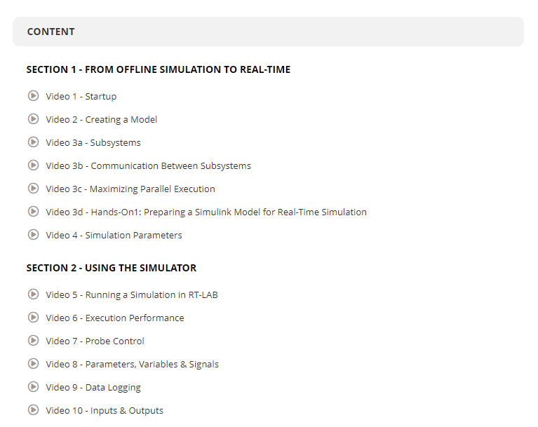
SECTION 1 – FROM OFFLINE SIMULATION TO REAL-TIME
• Video 1 – Startup (Preview)
• Video 2 – Creating a Model (Preview)
• Video 3a – Subsystems
• Video 3b – Communication Between Subsystems
• Video 3c – Maximizing Parallel Execution
• Video 3d – Hands-On1: Preparing a Simulink Model for Real-Time Simulation
• Video 4 – Simulation Parameters

SECTION 2 – USING THE SIMULATOR
• Video 5 – Running a Simulation in RT-LAB
• Video 6 – Execution Performance
• Video 7 – Probe Control
• Video 8 – Parameters, Variables & Signals
• Video 9 – Data Logging
• Video 10 – Inputs & Outputs

SECTION 3 – CUSTOMER SATISFACTION SURVEY
• Customer Satisfaction Survey


Get this course
Controller Architecture
Dashboard Building

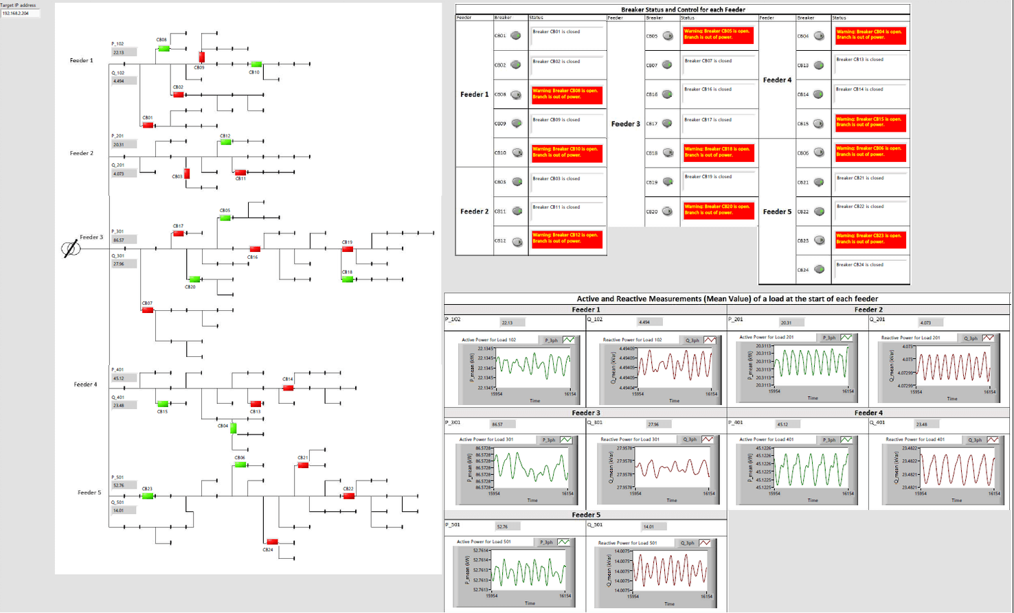
When HYPERSIM’s in-schematic signal monitoring is not enough, when networks are very large, or when more types of widgets are required, or even for training purposes, it may be practical to build distinct dashboards with a more concise organization of the information. Several tools can be used to achieve this, such as NI LabVIEW. Information is sent in real time from HYPERSIM using compatible communication protocols such as TCP/UDP or OPC UA and displays are refreshed every few milliseconds.

For a live demo using this functionality, watch this webinar
Dr. Flavia Khatounian

Abstract

Flavia Khatounian received her diploma in Electrical and Mechanical Engineering from Saint Joseph University of Beirut (USJ-ESIB), Lebanon, in 2002, and the Ph.D. degree in Electrical Engineering from the Ecole Normale Supérieure (ENS) de Cachan, France, in 2007. She joined the Saint Joseph University of Beirut in 2008 where she is nowadays a full-time associate professor at the Faculty of Engineering and Head of the Electrical and Mechanical Engineering Department.

Her research interests include power electronics and electrical machines identification and control. She serves as a reviewer for high impact factor journals and international conferences and is a member of the IEEE, IEEE Industrial Electronics Society (IES) and IEEE Robotics and Automation Society (RAS) where she volunteers currently as a vice chair of the Lebanon Joint Chapter, RA24/IM09/CS23 (CH08807). She is the author or coauthor of 2 book chapters and more than 40 scientific papers.

Emilio Piesciorovsky

Abstract

This study presents an interface method (IM) to interconnect real-time simulators (RTSs) without amplifiers for different intelligent electronic devices (IEDs), such as protective relays, smart meters, and other devices. It is a significant topic for the power systems protection community because there are many protection devices with different requirements. These protection devices have pinouts that measure bus voltages/currents and breaker pole states and generate trip/close pulse signals. Most of the emulation test beds with RTSs and HIL need amplifiers to connect IEDs from different product manufacturers because the low-voltage interface levels are not available in some instruction manuals. Additionally, commercial amplifiers have cutoff frequency limitations and have an excessive cost when several IEDs are wired onto test beds. Then, the validation of protection and control systems with RTSs and IEDs in the loop from different vendors without amplifiers results in an unfeasible alternative. In this paper, the IM was based on using an interface box, power source, and RTS to identify IED inputs/outputs. The sequence to recognize IED pinouts and calculate the current/voltage scaling factors is described. The IM was validated satisfactorily with RTS and a protection device (with unknown pinouts) in the loop.


Biography

Emilio C. Piesciorovsky graduated with a BS in electrical engineering from the National Technological University, Argentina (1995). He received his MS in marketing international from La Plata National University, Argentina (2001). He worked as an engineer for Pirelli Power Cables and Systems, SDMO Industries, ABB, and Casco Systems.

He completed his MS (2009) and PhD (2015) in electrical engineering from Kansas State University. Then, he worked as a postdoc at Tennessee Technological University and Oak Ridge National Laboratory.

Currently, he is a professional technical staff member and lab space manager in the power system protection area at Oak Ridge National Laboratory. He is the author/coauthor of more than 20 publications, and is an IEEE senior member; piesciorovec@ornl.gov.

Dr. Jean-Patric Da Costa

Biography

Jean Patric da Costa was born in Santa Maria, Brazil, in 1979. He received a B.S. degree in electrical engineering and a master’s and Ph.D. degrees from the Federal University of Santa Maria, Santa Maria, Brazil, in 2004, 2006, and 2011. He is currently a Professor with the Department of Electrical Engineering, Universidade Tecnológica Federal do Paraná (UTFPR), Curitiba, Brazil. His research interests include control of static converters, smart grids, ancillary services, and distributed generators.


Dr. Philippe Viarouge

Biography

Philippe Viarouge was born in Périgueux France in 1954. He received the engineering and Doctor of engineering degrees, the french accreditation to supervise research (HDR) from the “Institut National Polytechnique de Toulouse”, France, in 1976, 1979 and 1992.

Since 1979, he has been a professor with the Department of Electrical & Computer Engineering at Laval University, Quebec, Canada. He is working in the research laboratory LEEPCI. His research interests include the design & modeling of electrical machines and medium frequency magnetic components, AC drives and power electronics. He was Project Associate and consulting engineer at CERN, Geneva, Switzerland, in 2010 and 2018 respectively.


Dr. Ron Brandl

Biography

Dr. Ron Brandl completed his studies in electrical engineering in 2010 and received his doctorate in engineering from the University of Kassel in 2018. Since 2011, Ron Brandl is working as a research associate at the Fraunhofer Institute for Energy Economics and Energy System Technology – IEE, where he heads the group ‘Power Electronics Applications’ and is part of the Fraunhofer Competence Center ‘Cognitive Energy Systems’. Additionally, Ron Brandl is working as project manager and researcher at the European Distributed Energy Resource Laboratories e.V. – DERlab since 2018. His expertise covers topics such as real-time simulations, power hardware-in-the-loop technology, power electronics and system stability, electromobility and AI in energy. He is involved in the design of test centers for smart grids, participates in various national and European research projects, is part of several working groups, such as the IEEE Task Force “Real-Time Simulation of Power and Energy Systems”, the IEEE P2004 Working Group “Recommended Practice for HIL Simulation Based Testing” and he is National Expert and Operating Agent of the IEA-ISGAN Annex 5 “Smart Grid International Research Facility Network”.

Dr. Danielle Nasrallah

Biography

Danielle Sami Nasrallah received an Engineer’s diploma in electromechanical engineering and a Diplôme d’Études Approfondies in electrical engineering from École supérieure d’ingénieurs de Beyrouth (ÉSIB), Beirut, Lebanon in 2000 and 2002, respectively, and a Ph. D. degree in Robotics Modelling and Control from McGill University, Montreal, QC, Canada, in 2006. During her Ph. D. studies she worked on a part-time basis at Robotics Design as a control and robotics engineer. She moved to Meta Vision Systems in 2006-2007 as a control and applications engineer.

In 2008, she joined the electrical department of the Royal Military College of Kingston as an assistant professor and, in 2009, she was a visiting assistant professor at the American University of Beirut. From 2010 to 2014, she worked as a consultant in control and systems engineering. In 2014, she joined OPAL-RT TECHNOLOGIES where she is presently a technical lead in control and intelligent mobility. She retained links with academia as she lectures in Robotics and Control at both Concordia and McGill Universities.

Sebastian Hubschneider

Biography

Sebastian Hubschneider finished his studies of electrical engineering and information technology at the Karlsruhe Institute of Technology (KIT) in June 2015 with the academic degree Master of Science. During his time at the University, he specialized in power engineering with a focus on energy grids and the energy sector in general, including markets and the economy.

Since July 2015, Sebastian works as a research associate at the Institute of Electric Energy Systems and High-Voltage Technology (IEH), KIT. His research focuses on Power Hardware-in-the-Loop systems in conjunction with energy grids and electrical equipment.

Georg Lauss

Biography

Georg Lauss received the Dipl.-Ing. degree from the Johannes Kepler University JKU Linz, Austria, in 2006 and jointly from the Eidgenössischen Technischen Hochschule ETHZ, Zürich, Switzerland, and the Université Pierre-et-Marie-Curie, Paris, France. He is a researcher with the AIT Austrian Institute of Technology, Vienna, Austria. His main interests include electromagnetic systems, power electronics, system and control theory, mathematical methods for optimized control systems, hardware-in-the-loop simulation systems, and real-time simulation for electromagnetic power systems.

Georg Lauss is the Chairman of the IEEE WG P2004 Recommended Practice for Hardware-in-the-Loop (HIL) Simulation Based Testing of Electric Power Apparatus and Controls and the IEEE PES Task Force on Real-Time Simulation of Power and Energy Systems.

Dr. Charalambos Konstantinou

Biography

Charalambos Konstantinou is an Assistant Professor of Computer Science (CS) and Affiliate Professor of Electrical and Computer Engineering (ECE) at the Computer, Electrical and Mathematical Sciences and Engineering Division (CEMSE) of King Abdullah University of Science and Technology (KAUST), Thuwal, Saudi Arabia. He is the Principal Investigator of the Secure Next Generation Resilient Systems Lab (SENTRY) and a member of the Resilient Computing and Cybersecurity Center (RC3) at KAUST. His research interests are in secure, trustworthy, and resilient cyber-physical and embedded IoT systems. He is also interested in critical infrastructures security and resilience with a special focus on smart grid technologies, renewable energy integration, and real-time simulation.

He received a Ph.D. in Electrical Engineering from New York University (NYU), NY, in 2018, and a Dipl.-Ing.-M.Eng. Degree in Electrical and Computer Engineering from National Technical University of Athens (NTUA), Greece, in 2012. Before joining KAUST, he was an Assistant Professor with the Center for Advanced Power Systems (CAPS) at Florida State University (FSU). He is a Senior Member of IEEE, a member of ACM, and an ACM Distinguished Speaker (2021-2024).

Christine Van Slyke

Biography

Christine Van Slyke is Vice President of Global Sales and Marketing at SCALABLE Network Technologies. She has been with SCALABLE for over seven years and has a Masters in Business Administration. She has more than 20 years of experience in business, technology, and strategy development. Prior to SCALABLE, she spent more than a decade helping TELUS—one of Canada’s leading telecommunications and managed solutions providers expand its offerings across the Province of Ontario.

Deepak Fulwani

Abstract

This talk will discuss methods to implement different topologies of DC Microgrids.

José Eduardo Alves Junior

Abstract

Synchrophasor measurement technology is based on calculation of phasors obtained from Phasor Measurement Units. This technology is used in several countries to get better observability of electric systems. CEPEL’s Synchronous Phase Measurement Laboratory (LabPMU), in Cidade Universitária, Rio de Janeiro, RJ, is a laboratory infrastructure conceived to provide performance tests of PMUs and research on applications based on this technology. One relevant project carried out at LabPMU is to use Fractional Cycle Digital Fourier Transform Algorithm for Phasor Measurement Units (FC-DFT). This project aims to achieve faster PMUs, regarding the increasing presence of power electronics interfaced resources in power system generation and transmission. The presentation will show power electronic electrical simulations using HYPERSIM, in order to show the benefits of the algorithm. Two different simulation circuits were used: an HVDC multi-infeed circuit, as that arrangement is extensively used in the world, especially in Brazil; and a simulation of a distribution circuit provided with a PV array connected to the distribution electrical system through a converter (switching function model). Some occurrences of the power electronics equipment are simulated, and the results are the input of the FC-PMU. The FC-DFT results are then analyzed, showing that the equipment may deliver beneficial information for the control system operator and for early forensic analysis.

Aitor Ollacarizqueta

Abstract

CENER has developed an EMS to manage either microgrids or renewable generation plants hybridized with energy storage systems. Its first prototype has been validated at its facilities in the ATENEA microgrid, which have been previously simulated through RT-LAB using a OP4510 target.

The EMS consists of a SCADA where the user can configure almost any plant based on renewable generation systems, loads, electric vehicle, connection to utility grid, gen-set and different types of energy storage systems. Also, the EMS lets the user select between several strategies and plant control depending on the configuration chosen before and their interests.

Since the study focuses on the ATENEA microgrid, which is composed of lithium, flow and lead-acid energy storage systems, a gen-set, programmable loads, one electric car, solar generation and grid connection, this system has been modelled and then simulated in an OPAL-RT target.

Through a previous process of validation of every model as well as the communication system with the EMS, the built system allows to design, adjust, and validate the strategies and control systems before testing them in ATENEA.

Mike Mekkanen

Abstract

The development process of the microgrid controller (MGC) is that we first develop the controlling function in C that matches with the SIL preliminary algorithm developed by OPAL-RT/HYPERSIM. Secondly, a real HIL lightweight IED controller based on an iec61850 library is developed. Thirdly, we then test both the developed algorithm and the lightweight IED controller via various simulation scenarios. We perform testing scenarios of a developed MGS in a microgrid cyber-physical simulation subject to cyber-attacks in our lab. These testing are designed through performing two MGC testing scenarios. First, a delay attack is implemented, when the microgrid is islanded–the MGC monitors whole MG circuit breakers (CBs) specifically in this scenario—and the PCC CB should disconnect Load 4. Secondly, we test a packet manipulation on a measured data attack. External MGC HIL monitors the power generation as well as load consumption, in case (no balance) a trip command is issued to disconnect Load 3 via GOOSE. We then provide this development procedure for HIL MGC, which can communicate with the real-time simulator’s HYPERSIM simulation model over IEC 61850 GOOSE, as well as run the designed intelligent controlling algorithm and send the dispatching signal back to the real-time simulator model.

Shahab Karrari

Abstract

Low-inertia power systems can experience high rates of change of frequency and large frequency deviations during power imbalances. Inertia emulation using high power density storage systems such as a Flywheel Energy Storage System (FESS), can help limit the rate of change of frequency following sudden changes in generation or demand. In this presentation, a new adaptive inertia emulation controller for a high-speed FESS is proposed. To validate the behavior of the FESS with the proposed control design, the controller is implemented on a real 60 kW high-speed FESS, using the concept of rapid control prototyping. The performance of the FESS, equipped with the adaptive inertia emulation controller, is evaluated by means of Power Hardware-in-the-Loop (PHIL) simulations using the real-time simulation model of a low voltage microgrid. To reduce the overall loop delay, the established PHIL setup uses fiber optic connections to the power amplifier and several I/O expansion units. The State-space Nodal (SSN) solver is also applied to reduce the simulation time step of the microgrid model. The results of PHIL simulation show that the FESS with the newly-proposed adaptive inertia emulation controller outperforms the previously-suggested adaptive control designs, in terms of reducing the maximum rate of change of frequency and limiting the maximum frequency deviation, while not demanding significantly more energy from the FESS.

Matias Diaz

Abstract

Modular Multilevel Cascaded Converters (MMCC) have attracted considerable attention from the power electronic and drive research community since their introduction at the beginning of 2000. Originally, MMCCs were proposed for High-Voltage Direct Current (HVDC) transmission systems. Still, recently, they have been introduced into other fields, e.g., static compensators, wind energy conversion systems, and motor drives.

Among MMCCs, the Modular Multilevel Converter (M2C) is a well-established topology used extensively for HVDC transmission. However, the M2C has some difficulties in achieving good performance in applications where the electrical machine operates at a very low speed.

Therefore, other MMCC topologies, such as the Hexverter, the Modular Multilevel Matrix Converter, the Series-Shunt MMCC have been studied in the last few years. However, novel converters require complex implementations and control strategies that have hindered the number of works where experimental results of these topologies are reported.

In this context, this presentation introduces a joint project lead by the University of Santiago of Chile, in collaboration with OPAL-RT and Conecta Engineering, where a reconfigurable MMCC composed of 120 power modules is implemented using OPAL-RT MMCC modules. Thus, the testbed can perform rapid control prototyping testing and Power Hardware in The Loop analyses of novel topologies such as M3C, Hexverter and other novel topologies.

Catalin Gavriluta

Abstract

Smart grid applications, especially those focusing on the coordination of distributed flexibilities, include many devices governed by increasingly complex software architectures, all linked together by communication technology. In theory, some of these applications would have the potential to revolutionize the way the grid is being operated. However, in practice they are met with skepticism due to the uncertainties and vulnerabilities that these systems might introduce. Therefore, exhaustive testing and validation steps need to be undertaken before deployment to guarantee reliability. Approaching this task manually is extremely time-consuming and error prone. In this presentation we show an approach to automatically generate cyber-physical test beds which allow the evaluation of such applications. The proposed method uses PSAL (Power System Automation Language) to describe the cyber-physical system under test, i.e., the electrical network, the sensors, the actuators, as well as the various controllers/software components and their interconnections. Several model generators parse the PSAL code, and they automatically build a real-time simulation of the physical system; they establish various interfaces for the controllers to interact with the sensors and actuators; they package the controllers and deploy them to their designated locations; and they configure the data collection framework to enable the recording and analysis of experiment data.

Mukesh Singh

Abstract

The success of EVs depends on the charging infrastructure. Due to different charging standards, it is difficult for EV manufacturers to rely on any one standard. Therefore, there is a need to design a charging system which can fit in many charging protocols. This presentation will give an insight into the different charging standards and their probable solutions.

Balaji Mendi

Abstract

This paper presents the design and development of a wind turbine emulator (WTE), based on a separately excited DC motor, using an OPAL-RT digital simulator. The power-motor speed characteristics for different armature voltages in the motor are like the power-turbine speed characteristics for varying wind speeds in the turbine. WTE is a power electronic step-down chopper that is interfaced with a mathematical model of wind turbine present in the RT simulator. The wind turbine model generates a reference armature current that is compared with the actual armature current of the motor. The PI controller is used here to minimize the current error and provides a desired switching pulse to the MOSFET. The laboratory setup consists of a WTE that is coupled to a three-phase permanent magnet synchronous generator (PMSG) as a standalone system. The turbine model and PMSG model are presented in this paper. The effectiveness of this RT-LAB-based WTE is verified by simulation and experimental results under various wind speed and load change conditions.

Preeti Gupta

Abstract

Precision is the most important aspect for designing, controlling, or validating any power system—and due to this, real-time simulation is growing. Especially in design, it allows accurate modeling of a system, which is the baseline of design. Therefore, in this work, a switching function-based model of a three-phase voltage source inverter is transformed into a real-time model using OPAL-RT’s real time simulator (OP4510) with hardware-in-the-loop technology for its implementation in an actual power system. For the validation of its behavior in real time, it has been compared to the detailed inverter model having the same input variables and control dynamics. The results reveal that the proposed inverter model keeps the total harmonic distortion within limits as per the latest grid code and, at the same time, it maintains the required accuracy for the system. Further, this work shows the importance of real-time simulation by comparing its mode of simulation with other offline modes of simulations such as normal, accelerator and rapid accelerator.

Renzo Espinoza

Abstract

This work proposes an interfacing technique that uses the built-in three-phase transmission line models available in simulation platforms to perform Root Mean Square (RMS)-Electromagnetic Transient (EMT) real-time, multi-domain and multi-rate co-simulation. The main objective of this paper is to show the application of this kind of simulation in hardware-in-the-loop (HIL) testing of protective relays. Two well-known platforms are considered in this work: OPAL-RT with its ePHASORSIM tool is used for RMS simulation, and RTDS is used for EMT simulation. However, the proposed technique is sufficiently general to be applied to other real-time simulation platforms that have similar built-in transmission line models. To convert waveforms to phasors, a non-buffered rapid curve fitting method was implemented to attend to real-time constraints. During the testing phase of this research, tests for the HIL were completed using an actual transmission line protection relay. The presented results of tests highlight the benefits of the proposed interfacing technique.

Louis Filliot

Abstract

With the increasing level of penetration of renewable production and the need for long-distance energy transport, Multi-Terminal DC grids (MTDC) have become a crucial field of research for the future development of wide-scale DC grids.

These MTDC grids pose several technical challenges: protecting the DC grid against electrical faults; transforming DC voltage; and controlling the flow of energy in a meshed system. The possible technical solutions and new technologies addressing these issues need to be assessed through real-time and HIL simulations to demonstrate the system’s performance.

With that perspective, an MTDC HIL test bench is being developed at the Supergrid Institute to test and validate any proposed control and protection solution.

On this HIL setup, several Raspberry PIs are used to simulate in real time the different IEDs of the system: protection relays, station supervisors, DC Grid Control. These IEDs communicate with each other and with the electrical model using the IEC61850 communication protocol.

The electrical benchmark is a 4 Terminal DC Grid, modelled with HYPERSIM and running in real time with an OP5700 simulator.

The HYPERSIM model uses a Graphical User Interface (GUI), coded in Python and using the Python API provided by HYPERSIM. This interface allows a user to interact with the electrical system: launch a start-up sequence to connect the DC Grid, simulate a fault to test the implemented protection strategy.

Sanjeev Pannala

Abstract

The distribution system has undergone tremendous upgrades that have leaned toward a more carbon-free, reliable, and resilient infrastructure. This has been made possible by incorporating more sophisticated controllers in conventional generation, smart inverters based distributed generation, automatic load regulators, seamless interfacing of mini, micro and nano grids etc. To the contrary, the system is exposed to different events resulting from intermittent generation, as well as the unpredictable and uncertain behavior of loads in distribution networks. Real-time digital simulators from OPAL-RT let the power professionals study these events through digital twin models and by tweaking system parameters to create diverse and disruptive steady, dynamic, and transient event signatures–and also provides real datasets through the direct interface of sensors, PMUs, remote terminal units, smart measurement/meters, for testing and validating the AI-centric data analytics. Online testing of data analytical tools is made easy through real-time simulators by OPAL-RT as it has dedicated input and output digital/analog channels for export/import signals from/to power system models and supports standard communication protocols such as DNP3, C31.118-2011, etc. This presentation revolves around the wide usage of OPAL-RT’s real-time digital simulations in prospective testing environments of data analytics through real and simulated distribution phasor measurement units. Actual case studies are emphasized in the presentation.

Raju Chintakindi

Abstract

Wide Area Monitoring and Smart Automation (WAMSA) is today’s innovative research area under smart grid execution to overcome real-time protection difficulties. Modern communications and information processing technologies offer outstanding real-time benefits. The development of big data applications and satellite uplinks are rapidly changing. Several new measurement devices are being incorporated into an advanced smart grid metering infrastructure. In this process, PMUs can sense, converting signals from voltage and current into digital form under real-time wide-area monitoring systems. In modern power systems’ real-time applications point of view, big data analytics are playing a vital role with increasingly popular technological concept that contains smart electricity facilities, for instance, smart power control, energy utilization, and management. Initially, it emphasized smart grids, modern data analytics, massive-scale information control, and reliable monitoring methods with the extreme size of data required. This paper summarizes the PMU setup and installation overview in the Unified Real-time Dynamic State Measurement project (URTDSM) with the synchrophasor based wide-area monitoring system in India. The novelty of this presentation is to focus on big data potential functions and practices like fault detection, transient stability, load forecasting, and power quality monitoring into real-time wide-area monitoring.

Georg Lauss

Abstract

Part 1: The global power system’s transition to nearly 100% renewable-based generation presents new challenges not only in terms of control strategies but also in terms of tools required to perform HIL simulations. In this context, conventional generators such as synchronous machines may be gradually replaced by power electronic converters or similar generation units. HIL simulation setups of large grid models with multiple switching inverters are a challenge due to the high-level of accuracy required. The coupling of the power electronic domain with the network-level domain is currently the major issue to overcome. Two approaches are followed: the first one involves the coupling of the FPGA and the CPU model, while the second one uses the ARTEMiS library.

Part 2: Non-real-time or offline simulation methodologies using numerical solving techniques for network or component models have their limitations with respect to the necessity of high complexity. Therefore, they may prove insufficient with respect to resulting simulation accuracy or computation time. Real-time simulation based HIL simulation testing can overcome these issues, because physical hardware equipment, including the entire control system, is interlinked with the simulated network model via HIL interfaces. This enables natural coupling which guarantees the conservation of instantaneous power via the conservation of the through and across quantities at interfaces as exists in the real-world system.

Biography

Georg Lauss received the Dipl.-Ing. degree from the Johannes Kepler University JKU Linz, Austria, in 2006 and jointly from the Eidgenössischen Technischen Hochschule ETHZ, Zürich, Switzerland, and the Université Pierre-et-Marie-Curie, Paris, France. He is a researcher with the AIT Austrian Institute of Technology, Vienna, Austria. His main interests include electromagnetic systems, power electronics, system and control theory, mathematical methods for optimized control systems, hardware-in-the-loop simulation systems, and real-time simulation for electromagnetic power systems. Georg Lauss is the Chairman of the IEEE WG P2004 Recommended Practice for Hardware-inthe-Loop (HIL) Simulation Based Testing of Electric Power Apparatus and Controls and the IEEE PES Task Force on Real-Time Simulation of Power and Energy Systems.

Bolívar Escobar

Abstract

The advancement of technology has allowed the exponential development of electric engineering applications, and several of these fields are: digital simulation in real-time in conjunction with synchro-phasor measurements in electrical power systems; the generation of data applying the Monte Carlo method; and the analysis of data by application of data mining techniques. Research on load-shedding schemes, together with the application of the above-mentioned fields, allows the prediction of certain events that have caused the disconnections of large amounts of load, and even the operating output (blackout) of large power systems, around the world.

The present project proposes a methodology for the implementation of a load shedding scheme as a function of voltage and frequency that allows, through an indicator, and by means of an indicator calculated in real time through a previously-trained regressor, to determine the amount of load to be disconnected after the occurrence of a contingency for loss of generation.

To do this, a comprehensive real-time digital simulation platform is implemented, which uses OPAL-RT’s ePHASORsim, together with the functionalities of CENACE’s WAMS system, WAProtector, to execute a Software in the loop (SIL) to perform adaptive load shedding in real time, triggered when the indicator condition calculated by the regressor previously-trained with simulation results obtained from PowerFactory is met.

Ricky Zhang

Abstract

Our UPS HIL Testbench presentation will focus on how we used OPAL-RT’s solution in the UPS HIL system design to speed up the product launch, as well as key parameters Gs Understanding and TSB bridge usage in the UPS HIL system.

Isao Iyoda

Abstract

Japan intends on attaining carbon neutrality before 2050, and offshore wind farms are one of the primary energy sources that will help to realize this ambition. Since the sea depth around Japan is more that 50m, facilities of transmission systems for offshore wind farms must be installed on floating platforms. Middle frequency (500Hz) convertors are a promising equipment that reduce the weight and volume of transformers used for substations on the floating platform. MMC is a solution that can operate at 500Hz with less switching loss. It however requires much system analysis to develop and tune the control system. Real-time simulators are a useful tool for small academic laboratories to study on MMC. It saves risks of hardware trouble caused by mis-operation of the control system. An example of studies–such as the fundamental operations of scaled models (200V, 1A) of MMC convertors, real time simulation for tuning of control systems, as well as harmonics studies in our laboratory–will be introduced in the presentation

Highlight

Highlight Title

[DESCRIPTION]


Presented by:


[NAME]
[Title]
[Company]

[Optional Biography]


Register now
Demo

Demo Title

[DESCRIPTION]


Presented by:


[NAME]
[Title]
[Company]

[Optional Biography]


Register now